
Pneumatic Transport –
State of the Art – Desk research
Updated
16th May 2007 – Noel Hodson, Oxford.
Searches
of the World-Wide-Web:
Pneumatic Transport – State of the Art – Desk research.. 1
OUTLINE OF THE FOODTUBES
PROPOSAL. 5
USA - 230 MID-CONTINENT
TRANSPORTATION SYMPOSIUM 2000 PROCEEDINGS – HENRY LIU 6
EXECUTIVE SUMMARY – STATE OF THE ART FINDINGS. 6
1850’s TECHNOLOGY.. 6
NO DIRECTLY COMPARABLE SYSTEM... 6
SMALLER, SIMILAR SYSTEMS. 6
LARGE, HEAVY INDUSTRY,
CAPSULE SYSTEMS. 7
FOOD PIPELINES FOR POWDERED
FOOD.. 7
LARGE DIAMETER PIPES FOR OIL,
GAS AND WATER TRANPORT. 7
CAPSULES. 7
LOGISTICS and NETWORKS. 7
FLUID DYNAMICS. 7
PIGS AND SMART PIGS. 8
The Pneumatic Post of Paris
1866-2006. 8
Part 1. 8
Introduction. 8
The Parisian Network. 9
Today. 10
Pneumatic tube.. 12
From Wikipedia, the free
encyclopedia. 12
Pneumatic Post 13
Historical uses of pneumatic post 13
Current usage. 15
Present uses. 15
Powdered goods and powdered
foods: 16
EG 1 - FLSmidth-Pneumatic Transport 16
EG 2 – The ENGINEERING TOOL
BOX USA.. 16
EG 3 – Research in Germany - Pneumatic transport of
coarse grained particles in horizontal pipes 17
EG 4 – COAL DUST 17
Large Pipelines, Building and
Routing.. 18
Water
- 72inch (6 feet or 1.83 meters) Pipe. 18
Waste
Water – 90 inches or 2.28 meters pipe. 18
EUROPE - CONCAWE. 19
Europe: Assessment of Energy
Saving in Oil Pipelines (AESOP) 19
Overtrawling of large diameter pipeline trials JIP.. 22
Fishermen have been concerned in recent
years about the laying of large diameter pipelines in the North Sea. 22
Very Large Diameter FRP pipe
from Future Pipe Industries. 23
Floating Capsules. 25
Dynamic simulation of the motion of capsules in pipelines. 25
10 March 2000 - Loughborough University awarded
prestigious Personal Research Chair from the Royal Academy of Engineering and
BG Technology. 31
Supplies Uncertain for
Eastern Europe.. 31
Prof. Phil Hopkins Director, Centre for Pipeline Engineering. 32
http://www.ncl.ac.uk/marine/staff/profile/phil.hopkins 32
Pipeline Capsule Update.. 33
Russia.. 35
Third International
Specialized Fair – Kiev «Pipeline Transport — 2007». 36
Australia. 38
Segments -The major products
and services covered in this market research report are: Gas
pipelines Oil pipelines 38
Activities - The primary
activities of companies in this industry are:
The primary activities of firms in this industry comprise: 38
Netherlands. 38
Pipeline transport studies
and comparisons with road, rail and sea. 38
Electromagnetic drive - USA.. 39
Pipeline transport –v- truck
transport 40
Germany – Posch &
Partners. 41
Pipeline transport of bulk
materials. 41
Czech Republic.. 41
OGA Transporte Neumatico.. 42
ZVVZ a.s. Low Pressure
Transport 43
Low pressure transport 43
Medium pressure transport 43
High pressure transport 43
Pneumatic channel transport 43
Title: Pneumatic Capsule
Pipeline.. 43
March 26, 2001
(Computerworld). 47
Pnuetrans Systems Limited -
Toronto.. 49
TubeExpress 52
TUNNEL CONFIGURATION.. 53
OUTLINE OF THE FOODTUBES PROPOSAL
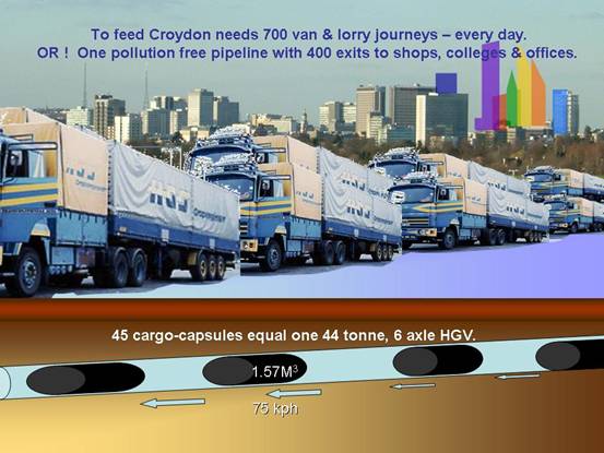
FoodTubes will, for example in the UK, build a circle or loop of pipelines of
1,000 kilometers or more, in which capsules will, for example, travel north up
the western arm and south down the eastern arm. The FoodTube
will link all major food distribution centres including farms, wholesale
markets, food factories and retail supermarkets. It is envisaged that flexible,
lightweight capsules will operate inside rigid pipes of 1 meter (3ft 3ins)
diameter and 2 metres (6ft 6ins) long. Capsules will have wheels or 3 or 4
bands around or embedded in them with roller-bearings in the bands; and the
capsules will have flexible collars at both ends, or a
single collar in the middle, to form an air-tight, non-rigid, low friction seal
with the pipes. The capsules will be, short-life, free running, be made of
flexi-materials to allow for slight bending, but are unlikely to be floating or
suspended by magnets, air or fluid in the pipes. The roller-bearings or wheels may be on
springs to deal with small, uneven pipeline blemishes.
The pipelines will be built of strong materials but
the capsules will be lightweight and disposable. Some capsules may be designed
to also serve as instant shop display cases to reduce handling, packing and
unpacking.
All capsules, empty or full, will travel round the
loop/circle of the pipeline. Each will carry an electronic address and
gate-control system which will open valves to conduct the vacuum/pressure air
flow to side-loops or exits for loading and unloading.
Air Pumps (possibly specially adapted LIMs (linear
induction motors) driving capsules, which in turn drive air flows) will be
located every 1/2 to 3 kilometers, depending on gradients. Thus each capsule is
subjected to pushing and pulling forces. Approximately 200 capsules of 2 metres
long spaced 3 metres apart will occupy a 1 kilometer
run of pipeline. The gradient, the weight of these capsules and the weight of
the volume of air in the pipeline will dictate the power of the pumps and the
engines that drive them. The pumps’ engines could be electric, drawing clean
energy from renewable power resources (tidal, wave, wind etc).
Internet Search Results:
USA
- 230 MID-CONTINENT TRANSPORTATION SYMPOSIUM 2000 PROCEEDINGS – HENRY LIU
Pneumatic
Capsule Pipeline.Basic Concept,
Practical
Considerations, and Current
Research
– by Henry Liu
Pneumatic
capsule pipeline (PCP) uses air blown through a pipeline to propel capsules
(wheeled vehicles carrying cargoes) through the pipeline. It is a modern and
large version of the century-old technology of “tube transport” used rather
widely and successfully in the first half of the 20th century in major European and U.S. cities for transporting mail, parcels,
telegraphs, documents, cash, and other lightweight materials.
Modern
PCP systems, such as those used in Japan for transporting limestone to a cement
plant, use large wheeled capsules moving heavy cargoes through pipes of 3-ft
diameter, approximately. Each capsule can carry almost two tons of cargo. The
system is driven by blowers located near the beginning of the pipeline, and it
is highly automated (by computers and programmable logic controllers). The
system is being used very successfully in Japan, with a high reliability
record. Yet, only limited use exists today due to its high unit freight
transportation cost in $/ton as compared to that by truck. The unit cost is
high due to low system throughput (freight capacity). Major improvement in
throughput can be made by replacing the pumping mechanism from blowers (which are
used currently), to electromagnetic pumps (for the future systems), and using
off-line loading/unloading. Research in such improvements of PCP is currently
underway at the Capsule
Pipeline Research
Center
at the University of Missouri-Columbia. Key words: capsule pipeline, PCP,
pneumatic capsule pipeline, tube freight, underground freight transport.
http://www.ctre.iastate.edu/PUBS/midcon/Liu.pdf
1850’s TECHNOLOGY: The vacuum
pipeline has been used since about 1850 and is widely known. It has been used
or proposed as a method for transporting goods and people for 150 years. Today there are pneumatic engineers in all
countries and pneumatic pipelines are used for a wide diversity of practical
purposes.
NO DIRECTLY COMPARABLE
SYSTEM: It seems there is no comparable
system in use, as working examples of the capsule system proposed for FoodTubes.
The flexibility and inexpensiveness of
using road vehicles (low wages and low fuel prices) has discouraged investment
into alternative transport for the past 50 years or more. The most similar,
recent conceptualization seems to be by scientist Henry Liu in the USA
(see INDEX) http://www.ctre.iastate.edu/PUBS/midcon/Liu.pdf
SMALLER, SIMILAR SYSTEMS: The Paris pneumatic postal
system transports capsules of about 8cms ( 3 inches)
diameter carrying packets around an extensive network of tens of kilometers.
The capsules are ten times smaller than envisaged for FoodTubes and have no
wheels or roller-bearings. In modern times the capsules are fitted with
electronic addressing systems. Such systems date back to 1850 and are well
understood.
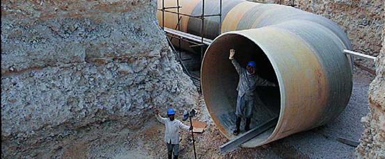
LARGE, HEAVY INDUSTRY, CAPSULE
SYSTEMS: There are numerous examples of 1 metres
diameter capsules being used in modern industry to carry ore, coal and similar
cargos through vacuum pipelines. The capsules are made of heavy duty iron,
steel or aluminium, to cope with the heavy contents,
and run on wheels.
FOOD PIPELINES FOR
POWDERED FOOD: There are many modern examples in the food industry of powders being
blown into suspension in air streams and transported at speeds of 20-40 KPH
around factory sites. Such air-stream systems are also found in the chemical
industries. Air-stream suspensions are particularly useful for feeding mixers,
grinders and furnaces – e.g. coal dust being fed into fires.
The technology for these processes is modern and
evolving. Pipes are generally narrow and no larger than 15cms (6 inches)
diameter. FoodTubes can probably benefit from the knowledge of valves and
switching air flows, used in the industry.
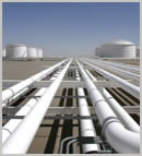
LARGE DIAMETER PIPES FOR
OIL, GAS AND WATER TRANPORT: Technology for transporting
water, sewage and oil & gas through large diameter pipelines over long
distances is sophisticated and constantly evolving. Modern pipelines of up to 3 metres diameter
are laid or constructed in various parts of the world. The know-how is current
in the civil-engineering industry.
CAPSULES: There seems to
be little modern technology concerned with making, directing and addressing
capsules. Perhaps some of the knowledge needed for FoodTubes can be found in
the maintenance sector which makes “pigs” and “smart pigs” – that are sent
through pipelines to clean and repair them. Capsules that “float” within pipelines on
cushions of fluid, air and electromagnetism are in use but FoodTubes may be
able to rely on simple, lightweight capsules running on bearings or wheels.
LOGISTICS and NETWORKS: FoodTubes will rely heavily on the skills of
the transport industry in planning routes and in the skills of the computer
industry. Both are highly active and accessible.
FLUID DYNAMICS: Pushing air
through pipes, with and without capsules, is a part of the science of fluids.
This discipline dates back thousands of years and the mathematics and laws that
govern fluids are well understood.
pig
A pig, also known as a “smart” pig, is a generic term signifying any
independent, self-contained device, tool, or vehicle that is inserted into and
moves through the interior of a pipeline for inspecting, dimensioning, or
cleaning. These tools are commonly referred to as ‘pigs’ because of the occasional squealing noises
that can be heard as they travel through the pipe.
RICE UNIVERSITY - Several inline pipe inspection
systems dominate industry. The most common systems used are “pigs” or “smart pigs” that utilize fluid
pressure to flow along the pipeline and can reach velocities of up to seven
miles per hour depending on driving pressure. Different types of pigs serve a variety of
functions such as batching or separating dissimilar products, cleaning pipes,
and inspecting internal pipe surfaces. They have a simple structure, are
economical to use, and thus many large
pipelines are currently designed with pigging maintenance in mind. however, pigs
must have high fluid pressure, cannot stop at arbitrary distances, and cannot maneuver through various pipe configurations such as
elbows. Inspection pigs
utilize drive cups on their front to transfer fluid pressure into a driving
force. Thus, inspection pigs
must have a diameter close to that of the pipe ID and they may get stuck due to
material buildup or pipe deformations. To maintain
high enough fluid propulsion, inline inspection pigs are usually large (24 inches to 36 inches
in diameter) with the smallest commercially available pig 6 inches in diameter
[2].
They cannot get through smaller pipes, tight turns,
and some valves. Other types of
commercially
available inline pipe inspection systems include tethered robots, which have
limited range and mobility
by J.D. Hayhurst
O.B.E.
Edited by C.S. Holder
Prepared in digital format by Mark Hayhurst
Copyright © 1974. The France & Colonies Philatelic Society of Great Britain.
Part
2 of 3
Part
3 of 3
The first
half of the 19th century saw an unprecedented acceleration of communication
through the introduction of the electric telegraph. Its principal application
was to commercial intelligence for the merchants on the stock exchanges for
whom fortunes could be won by the receipt of advance information, but the gain
in speed from the telegraph could be lost if a message took a long time to get
from the telegraph office to the stock exchange. It was to avoid this delay
that in 1853 J. Latimer Clark installed a 220 yard long pneumatic tube
connecting the London Stock Exchange in Threadneedle Street
with the Central Station in Lothbury of the Electric
Telegraph Company which had been
incorporated in 1846. There were similar installations in Berlin
in 1865 between the Central Telegraph Office and the Stock Exchange, and in
1866 in Paris
out of the place de la Bourse.
Other cities
followed and tube systems were opened not only for the transport of telegrams
but also for individual letters and for letters in bulk. The transport of
letters in bulk required large diameter tubes such as exist today in Hamburg and as once
existed in a number of American cities. Provision for the transport of
individual letters was made in Vienna and Prague, Berlin, Munich, Rio de Janeiro, Rome, Naples, Milan, Paris and Marseilles. There were
ephemeral installations for private letters at the South Kensington Exhibition
of 1890, at the Karlsbad Philatelic Exhibition of
1910, and at the Turin International Exhibition of 1911.
Today, the
pneumatic post survives only in Paris and Italy.
Pneumatic tubes are still however widely used for the transport inside many
cities of the world of small batches of telegrams, express letters and air mail
letters. These tubes are generally of a diameter of about 3 inches and the messages
are carried in cylinders which are propelled along the tube by an air pressure
differential from the back to the front, attaining speeds of around 25 mph.
Letters and cards which have been transported in the tubes are invariably
creased where they have been rolled up for insertion in a cylinder.
The network
in Paris was
commenced in 1866 by the construction of an experimental line between the
telegraph offices at Grand Hotel and place de la Bourse. This was extended in
1867 into a one-way hexagon from place de la Bourse through the telegraph
offices rue Jean-Jacques Rousseau, rue de Rivoli, rue
des Saints-Peres, the Central Telegraph Office (rue de Grenelle),
rue Boissy d'Anglas, and
back to Grand Hotel. During the following decade single line polygonal systems
were linked to this hexagonal system and a double tube (two-way) was laid
between Central and Bourse, but the network remained always within the limits
of the pre-1791 octroi of Paris, roughly corresponding to the inner arrondissements.
Figure 1. Map of the Parisian Pneumatic
Post Network.
In 1879, with the
opening of the service to the public, there was a new motive for expansion and,
in 1881 plans were approved to extend the network of tubes across the whole of Paris. There were to be
four stages each taking about one year to achieve: by 1 February 1882 the 16th
and parts of the 15th and 17th arrondissements;
by 1 April 1883 the rest of the 17th, the 18th, and part of the l9th; by 1
February 1884 the rest of the l9th, the 12th and 20th; by 15 December 1884 the
rest of the 15th, the 13th and 14th. The system of tubes running across the
whole of Paris (generally located in the sewers) consisted of tubes of 65 mm
diameter but from 1888 many tubes of 80 mm diameter were installed and today
about one-third of the system uses the larger diameter. Also from 1888 began
the elimination of the one-way polygonal networks and their replacement by
double tubes.
Since the end of
the l9th century there have been numerous detail changes of the network inside Paris but only one tube has gone outside Paris:
that to Neuilly
opened in 1914. It had been intended to extend the tubes widely through the
suburbs but the 1914-18 war suspended the project and it was never revived.
Nevertheless, in 1907 the transport of pneumatic mail beyond the limits of Paris was made possible by
the employment of special messengers operating in 19 suburban areas. By 1916
these messengers were on bicycles and operating in most of the towns of the
department of the Seine and also in Enghien-les-bains,
Sevres, and St Cloud in the department of the
Seine et Oise.
Raincy was added in 1921.
Today, the service works inside
Paris and to Neuilly by the
tubes and thence outwards throughout most of the suburbs by messengers on
motorcycles. Inwards the service uses post office vans between the suburban
post offices and those offices on the limits of Paris which are on the tube network.
There is also
another network between French government offices radiating from Central but
with one line joining the Senate and the -Assemblee Nationale with the Journal Official. Along this line pass
the transcripts of the parliamentary debates which are printed and published
within twenty-four hours.
The cylinders are
propelled along the tubes pneumatically, ie by air
either compressed or depressed: they are either blown forwards or sucked
forwards from one office to another. The pressures come from compressors
feeding groups of offices; these compressors were originally simple heads of
water, then driven by steam engines, and finally by electrical machines. There
are today 7 such installations, supplying pressure to 12 offices in the network.
For a long time
the cylinders went from one office to the next where their contents were sorted
for the next stages of their journeys. Much time was spent in the manual
redirection of cylinders but, after experiments in 1931, automatic navigation
was introduced using apparatus which could accept or pass on cylinders
according to the setting of electrically conducting bands encircling the
cylinders.
Figure 2. Pneumatic Post cylinders, new and old, showing the
electrically conducting bands introduced after 1931.
The administration
of the senice started with the Télégraphes since
it was then intended for the transport of telegrams and the first network
connected offices of the Télégraphes which
were quite distinct from those of the Postes. In 1878
the Postes and
the Télégraphes were
joined and became the Postes et Télégraphes. Later,
the Télephones was added to make the P. T. T.
which still today remains the familiar designation of the Postes et Télécommunications. Inside the larger
organisation, the responsibility for the pneumatic service remained with the Télégraphes or its successor the Télécommunications. The cooperation between the
separate parts of the ministry is well illustrated by the events of 1927 when
floods put the Segur telephone exchange out of
action; telephone subscribers were allowed to send letters by tube for 30
centimes, the cost of a telephone call, instead of the normal 1.50 franc
charge. Although not operated by the Postes,
the service must still be considered to be postal
since the addressee receives the original manuscript (or typescript) message of
the sender on a letter, or card, or letter-card each of which falls within the
generic term 'pneu'.
The service does
not have its own offices but pneus are posted in
special boxes which have slits narrower than those for conventional mail. The
fusion in 1878 of the Postes and
Télégraphes led to a rationalisation of their of fines and the purely telegraphic of fines gradually
disappeared. At the end of 1879, the first year of public use of the pneumatic
tubes, there were 36 of fines in Paris
with pneumatic installations but only 6 of them provided a postal service;
before the end of the century all solely telegraph offices had been closed. The
telegraph of fines had been numbered serially in 1871 and the post of fines in
1863; as the two merged the joint offices took the postal number. Up to their
individual closures the few telegraph offices which remained were allotted
postal numbers as, for example, Ecole Militaire,which had had the number
15 as a telegraph of fine in 1871, was given the number 46 in the postal series
until its closure in 1891. These office numbers had a purpose: an instruction
of 1871 required that each telegram (and hence, later, each pneu)
should carry in its top left-hand corner the two digit number of the office of
despatch preceded by the number of that telegram as recorded in the daily
register. Thus the 341st pneu sent out on one day by
Bourse (98) would carry 34198. Since the first nine post
of fines were numbered only by a single digit their telegraph counters used the
post office numbers preceded by a zero. These office numbers were not initially
used to indicate the destination of a pneu. At the
office of posting, the name of the office nearest the addressee was written in
the top left hand corner so as to facilitate its navigation through the tube
network; just after the turn of the century there was a gradual replacement of
the office name by the office number.
There was a
curious situation in 1900 when the seven post of fines
at the International Exhibition were temporarily allotted telegraph office
numbers from 10 to 16, numbers which were being used at the same time by the
normal Paris
post of fices 10 to 16. To avoid confusion, the pneus from these of fines were recorded in each daily
register starting at 501; thus the 27th pneu sent out
on a particular day from Alma
(12) would carry 52712.
Shortly
afterwards, the practice of numbering pneus was
discontinued.
Part 2 of 3
Jump to: navigation, search
Pneumatic tubes,
also known as capsule pipelines or Lamson tubes,
are systems in which cylindrical containers are propelled through a network
of tubes by compressed air or by vacuum. They are used for transporting
physical objects.
Pneumatics can be traced back to Hero of Alexandria in the 1st century AD. The Victorians used capsule pipelines
to transmit telegraph messages, or telegrams, to nearby buildings from
telegraph stations.
While they are
commonly used for small parcels and documents - now most often used at banks or supermarkets - they were originally
proposed in the early 1800s for transport of heavy freight. It
was once envisioned that networks of these massive tubes might be used to
transport people.
Pneumatic post
or pneumatic
mail is a system to deliver letters through pressurized air
tubes. It was invented by the Scottish engineer William Murdoch in the 1800s and was later
developed by the London Pneumatic Dispatch Company.
Pneumatic post systems were used in several large cities starting in the second
half of the 19th century, but were largely abandoned
during the 20th century.
It was also
speculated that a system of tubes might deliver mail to every home in the US. A
major network of tubes in Paris was in use until 1984, when it was finally abandoned in
favor of computers and fax machines. In Prague, Czech Republic, a network of approximately
60 kilometers for delivering mail and parcels still exists. However, due to
damage sustained during the 2002 European floods the service has been
put on indefinite hiatus.
Typical current applications are in banks and hospitals. Many large retailers (such as
Home Depot or CostCo in the US) use pneumatic tubes to
transport checks or other documents from cashiers to the accounting office. One
system lists a speed of 10 m/s. [1]
Pneumatic post
stations usually connected post offices, stock exhanges,
banks and ministries. Italy
was the only country to issue postage stamps (between 1913 and 1966)
specifically for pneumatic post. Austria,
France, and Germany
issued postal stationery for pneumatic use.
- 1853: linking the London Stock Exchange to the
city's main telegraph station (a distance of 220 yards)
- 1865: in Berlin
(until 1976), the Rohrpost,
a system 400 kilometers in total length
- 1866: in
Paris
(until 1984, 467 kilometers in total length from 1934)
- 1875: in
Vienna
(until 1956)
- 1887: in
Prague
(until 2002 due to flooding), the Pražská potrubní pošta,
[2] (in Czech, with pictures)
- other
cities: Munich, Rio de Janeiro, Hamburg, Rome, Naples, Milan, Marseilles,
Boston, New York City, Philadelphia, Chicago, St. Louis
(Pneumatic Transportation of People
Here refers to the
transporting of people inside pneumatic tubes; other forms of transportation
that use pneumatics for propulsion are not considered.)
In 1812, George Medhurst
first proposed, but never implemented, blowing passenger carriages through a
tunnel.
Brunel built
an atmospheric railway on an 83.7-kilometre section of the South Devon Railway between Exeter and Plymouth, England in the 19th century It was also tried on the London & Croydon Railway
in 1845, but was soon abandoned.
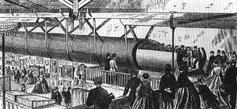
In 1861, the London Pneumatic Despatch Company
built a system large enough to move a person, although it was intended for
parcels. The October 10, 1865 inauguration of the new Holborn Station
was marked by having the Duke of Buckingham, the chairman, and some
of the directors of the company blown through the tube to Euston (a five minute trip).
A 550 metre (m) pneumatic passenger railway was
exhibited at the Crystal Palace in 1864. This was a prototype for a proposed Whitehall
Pneumatic Railway that would have run under the River Thames linking Waterloo and Charing Cross. Digging was started in 1865 but was stopped in 1868 due to financial problems.
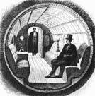
In 1867 at the American Institute exhibition in New York, Alfred Ely Beach demonstrated a 32.6 m
long, 1.8 m diameter pipe that was capable of moving 12 passengers plus
conductor. In 1869, the Beach Pneumatic Transit Company of New York constructed in secret a 95 m long,
2.7 m diameter pneumatic subway line under Broadway. The line only operated for a few
months, closing after Beach was unsuccessful in getting permission to extend
it. (Though widely believed to have been demolished to make way for the current
subway system, some think the system may
still exist buried beneath the city. An old pneumatic tunnel is seen in the
theatrical movie Ghostbusters 2 and in the direct-to-video
movie An American Tail: The Treasure of
Manhattan Island.)
In the 1960s, Lockheed and MIT with the United States Department of Commerce did
feasibility studies on a vactrain
system powered by ambient atmospheric pressure and "gravitational pendulum
assist" to connect cities on the East Coast of the US. They calculated
that the run between Philadelphia and New York City would average 174 metres per second.
When those plans
were abandoned as too expensive, Lockheed engineer L.K. Edwards founded Tube Transit, Inc. to develop
technology based on "gravity-vacuum transportation". In 1967 he
proposed a Bay Area Gravity-Vacuum Transit for California that would run along side the
then-under-construction BART system. It was never built.
The technology is still used on a smaller scale. A large
number of drive-up banks use pneumatic tubes to transport cash and documents
between cars and tellers. Most hospitals have a system to deliver drugs,
documents and specimens to and from laboratories and nurses' stations. Many
factories use them to deliver parts quickly across large campuses. Many larger
stores use systems to securely transport excess cash from checkout stands to
back offices, and to send change back to cashiers. NASA's original Mission Control Center in Houston, Texas
had pneumatic tubes connecting controller consoles with staff support rooms. Denver International Airport is noteworthy
for the large number of pneumatic tube systems, including a 10-inch diameter
system for moving aircraft parts to remote concourses, a 4-inch system for
United Airlines ticketing, and a robust system in the parking toll collection
system with an outlet at every booth.
Present uses:
P neumatic
transportation uses compressed air for propulsion; air is blown through an
airtight tube, propelling a capsule, canister or other vessel. It has had some
success, although efforts to use it to transport people have failed.
Pneumatic transportation dates back to the 1860s,
when engineer T.W. Rammel won a huge contract with
the British Post Office for a network of pneumatic tubes to carry mail
throughout London.
By the turn of the century, New York City had an
extensive system that moved letters and parcels in a loop around Manhattan, with an extension into Brooklyn.
Enough pressure was used to propel a canister containing 700 letters at 30
miles per hour. Boston, Chicago,
Philadelphia and St. Louis all employed pneumatic systems for
mail distribution. By the 1950s, all of the systems had been abandoned in favor of newer technology – trucks.
Pneumatic systems on a smaller scale were used in
retail stores, where a salesclerk would forward a customer’s money to a central
cashier in a small canister; change and a receipt would be returned via the
canister.
A pneumatic system to transport people was developed
by Alfred E. Beach in New York City
in 1870. Using his own money and operating in secrecy, Beach managed to dig a
block-long subway tunnel right across from City Hall. A huge rotary blower,
dubbed the Western Tornado, produced one hundred thousand cubic feet of air per
minute and drove the subway car at about ten miles an hour on a gentle cushion of
air. The public clamored by the thousands to pay $.25
to ride the pneumatic subway which featured a luxurious car, complete with
upholstered seats, oil paintings and chandeliers.
While it captured the public’s fancy, the high cost
of producing enough air to transport trains, along with the difficulty of
controlling the pneumatic power for the frequent stops needed for a subway
line, doomed Beach’s effort. Such economic and technical failures are common to
transportation futuristics.
Previous failure did not deter Lockheed engineer L.K.
Edwards from trying to resurrect the idea of a high-speed tube transport in the
1960s. Lockheed eventually decided to drop its research in this area, but
Edwards persisted, forming Tube Transit, Inc. to exploit “gravity-vacuum
transportation.” He made presentations to federal and local transportation
officials extolling the virtues of his concept, but his pneumatic subway
ultimately was no more successful than Alfred Beach’s.
Pneumatic transportation survives today as a means
for moving commodities, usually through pneumatic capsule pipelines (PCPs).
Research is focused on developing larger diameter pipelines with greater
capacity, but the problem of how to compete economically with freight movement
by truck or rail persists.
http://www.lib.berkeley.edu/news_events/futuristics/pt/
There are numerous modern systems which pump powders
without capsules through pipelines. The pipes tend to be relatively narrow,
less than 12inches diameter. The powders are suspended in jets of air and are
usually transported short distances within industrial complexes.
EG 1 - FLSmidth-Pneumatic
Transport is a worldwide leader in pneumatic bulk conveying
for the process and materials handling industries. We offer
innovative technology and broad experience in all aspects of material handling
systems.
Our experience speaks for itself. Since Fuller
began in 1926, our pneumatic conveying systems have moved millions of tons
of dry bulk solids in numerous applications.
Up-to-date technology and proven equipment are only
two of our strengths:
We excel at system engineering, designing and
installing complete bulk material transfer systems.
Let us put our experience to work for you.
EG 2 – The
ENGINEERING TOOL BOX USA - Some common
solids as flour, sugar, cement and many more, can be
suspended and transported in air - referred as pneumatic conveying. A pneumatic
conveying system may transport solids up to approximately 50 mm size. The
powder or solid must be dry, with no more than 20% moisture and not sticking.
In a pneumatic conveying system, most of the energy
is used for the transport of the air itself. The energy efficiency of a
pneumatic conveying plant is therefore relatively low, but this is often
outweighed by easy handling and, in well designed systems, dust free solutions.
In general the length of a pneumatic system should
not extend 300 m for each pneumatic unit. The products can be conveyed over
long distances by connecting the systems in series.
There are three basic designs of pneumatic transport
systems:
·
dilute phase conveying at a high gas speeds (20 - 30
m/s)
·
strand conveying at a limited gas speeds (15 - 20
m/s)
·
dense phase conveying at a low gas speeds (5 - 10
m/s)
Pneumatic systems can operate with both positive and
negative pressures - vacuum. The working pressure should not extend 40 kN/m2.
The maximum temperature rise during pneumatic
compression is seldom above 5oC, which makes pneumatic transport
systems suitable to sensitive products as medicines, food or similar.
Authors: Molerus O.1; Heucke U.
Source: Powder Technology, Volume 102, Number 2, 3 March 1999, pp. 135-150(16)
Publisher: Elsevier
Keywords:
Pneumatic transport; Coarse grained particles; Elevated static pressure; Plugging limit; Strand flow type of conveying; Fully suspended type of conveying; Self-sustained particle transport; Pressure drop
Language: English
Document
Type: Research article
DOI: 10.1016/S0032-5910(98)00204-6
Affiliations: 1: Lehrstuhl fur Mechanische
Verfahrenstechnik, Universitat
Erlangen-Nurnberg, Erlangen, Germany
EG 4 – COAL DUST - The
use of pulverised coal in integrated gasification combined cycle (IGCC) power
plant is currently under development. The results of a project to determine the
suitability of Chinese coals for dry feed to the entrained flow gasifier that forms part of the above cycle are presented.
This paper also includes some basic material characterisation of the pulverised
coal.Pneumatic conveying test rigs were used in
conjunction with a mathematical model to generate conveying characteristics for
coal at high back pressures. The overall strategy was to test both coal and
surrogate at atmospheric back pressure to compare the two materials'
performance, under similar conveying conditions; and to test the surrogate
material at elevated back pressure, and use this data to validate a
mathematical model. The similarity of behaviours of the two materials then
allowed the model to be applied to the data measured for coal and so generate
conveying characteristics at conditions typical of entrained flow.The mathematical model used to scale the results to
high back pressures, which characterise entrained flow processes, is based on
the assumption that the influence of the pressure drop due to solids is
independent of the back pressure, in the range of conditions considered.
Conveying characteristics were generated at a variety of back pressures ranging
from 1 to 25 bar. A brief analysis of the minimum
conveying velocity is also presented. Authors Cowell A, Mcglinchey D,
Ansell R
Water
- 72inch (6 feet or 1.83 meters) Pipe - In 1998 it was determined the population growth rate in the service
area of the North Texas Municipal Water District’s (NTMWD) North System would
eclipse the population and demand projections. It was decided an additional
parallel transmission line was needed to serve the increased demands of the
region. The first parallel line needed was a 72-inch transmission line
approximately seven miles in length through mostly developed subdivisions and
crossing under two major highways, State Highway 121 and US-75. State Highway
121 is currently being widened to a six-lane highway with frontage roads and
US-75 is currently a six-lane highway with frontage roads. Multiple routes were
considered for the construction of the Allen/Plano/Frisco/McKinney 72-inch
Pipeline. The route chosen had the most impacts to existing roadways, highways,
utilities and subdivisions. Even with the number of impacts, it was chosen
because it was the shortest and most economical route. The route is along the
median of Exchange Parkway
in the City of Allen
which currently is a four-lane divided roadway with a future six-lane section
at build out. The pipeline was constructed under the two major highways within
a 90-inch tunnel totaling 1250 feet. The SH 121
crossing was especially challenging because it crossed under five, six foot by
nine foot multiple box culverts and was located under a 16 foot high retaining
wall at a bridge approach for the main lanes of State Highway 121. The pipeline
was split in two bid packages, Phase I and Phase II. The first phase was bid in
the fall of 2004 and was awarded at $13,197,000 and the second phase was bid in
the fall of 2005 at a cost of $8,813,000. This paper discusses the methodology
used in the pipeline route selection process and the design and construction
issues associated with construction of a large diameter pipeline in a highly
urban setting.
Waste
Water – 90 inches or 2.28 meters pipe - The Interconnect Pipeline Project is one of three projects that make
up the San Antonio Water System (SAWS) Interconnect Program. CH2M HILL was the
designer for the Interconnect Pipeline Project and also provided construction
inspection services. This project and two others were combined into a single
active construction program for which CH2M HILL was selected to provide
construction management services. The Interconnect project includes
construction of a 16,300 foot (4,968m) 90-inch (228cm) raw wastewater transfer
pipeline, a 13,500 foot (4,115m) 36-inch (91cm) recycled water line and 20,000
feet (6,096m) of fiber optic cable. The second
project, the Interconnect Modifications Part B, includes raw wastewater
connections at the Salado Creek WRC and the Dos Rios
WRC. The third, the Dos Rios Recycled Water Pump Station Project, consists of a
recycled water pump station at the Dos Rios WRC, and a recycled water pipeline
terminal connection at the Salado Creek WRC. The
primary purpose of this project is to link the Salado
Creek WRC and the Dos Rios WRC together to optimize future operations. The project
will allow the transport of raw wastewater to the Dos Rios WRC from the Salado Creek sewershed. At
present, the Dos Rios WRC has excess treatment capacity. The link will allow
SAWS to decommission the Salado Creek WRC, thereby
saving approximately $5 million per year in operating costs. The recycled water
pipeline will permit the use of Dos Rios WRC treated wastewater in the San Antonio recycled water
system. This will maximize the yield of recycled water from SAWS’ wastewater
treatment facilities. The fiber optic carrier
included in the Salado
to Dos Rios Interconnect Project will provide for the future Installation of
DCS between the two water recycling centers.
EUROPE - CONCAWE:
Pipelines are
a long-established safe and efficient mode of transport for crude oil and
petroleum products. They are used both for short-distance transport (e.g.
within a refinery or depot, or between neighbouring installations) and over
long distances. An extensive network of cross-country oil pipelines in Europe meets a large proportion of the need for
transportation of petroleum products.
For more than
30 years CONCAWE has been collecting facts and statistics on incidents and
spills related to European cross-country pipelines. A yearly report is
published and a special report was issued in 2002 compiling 30 years of
pipeline performance statistics and including a map of Refineries & Oil Pipelines in Western Europe.
Other activities in this area include responding to various legislative
initiatives concerning pipelines, particularly from the European Commission, but also from national governments.
This field of CONCAWE's activity is open to all
companies operating oil pipelines in Europe,
whether or not they are a CONCAWE Member Company.
It provides a forum for the exchange of information between pipeline operators
on technical progress and lessons to be learnt from incidents. In addition, a
COPEX (CONCAWE Oil Pipeline Operators Experience Exchange) seminar is organised
every four years for the benefit of all pipeline operators in Europe.
Europe: Assessment of Energy Saving in Oil
Pipelines (AESOP).
Objectives and problems to be solved:
Oil transportation companies are experiencing a need to increase their
efficiency and transport capabilities. It has been shown that the frictional
pressure drops or drags, responsible for energy losses and limiting the
throughput of oil pipelines, can be significantly reduced by injecting
long-chain polymers (the so called flow improvers). However, the technique is
not widely used by oil-pipeline companies because of the lack of design and
operation knowledge at industrial scale.
The main objective of the project is to reduce the energy consumption and
to increase the transport capabilities of oil pipeline networks by developing
the techniques required to use long-chain polymers as Drag Reducing Agent (DRA)
in European oil pipeline networks.
Description of work:
The research activity starts with experimental studies of the effect on
oil product characteristics when high DRA rates are added. This task also
includes the laboratory tests and analysis necessary to determine how
long-chain polymers can be broken and the study of the effect on internal
combustion engine and others parts of the vehicle.
In parallel, large scale experimental studies of the efficiency of long
chain polymers on pipeline oil transportation systems with low DRA rates are
carried out (oil products properties are not affected with these low rates).
Different pipe diameters, polymer concentration and products are taken into
account. At conclusion of this task, the same experimental studies are done
with higher DRA rates. The data obtained serves as a basis for obtaining a
model of how the polymers behave and how the injection rate affects the
operation. Once the model is developed, a methodology for the use of polymers
is established, considering specific instrumentation and computer aided design
programs to establish the optimum design parameters regarding number of
injection points and quantities to be injected and the optimal way of operating
the pipelines.
Expected results and exploitation plans:
The expected results of the project are computer programmes for designing
and optimal operation of oil pipelines using DRA as well as an assessment of
the benefits obtained by the technique. The expected results in the
installations are a reduction of more than 25 % in the energy required for
ton-km of the base products and an increase in the capacity of more than 30 %
in terms of ton-km.
A reduction of the oil transport cost will imply a reduction of the price
of energy and this will contribute towards the competitiveness of the oil
pipeline partners and of Europe and on
employment prospects in general. The increasing transport capabilities that can
be obtained with this technology could make other transport solutions, mainly
truck fleet, become only marginal. An important social benefit can be obtained
combating the saturated European road and highway system.
The results will be exploited by the two end-users in their own pipelines
and also by selling the developed software to other companies.
Revolution,
geopolitics and pipelines
By F William Engdahl
After a short-term fall in price below the $50 a barrel level, oil has broken
through the $60 level and is likely to go far higher. In this situation one
might think the announcement of the opening of a major new oil pipeline to pump
Caspian oil to world markets might dampen the relentless rise in prices.
However, even when the Organization of Petroleum Exporting Countries agreed on
June 15 to raise its formal production quota by another 500,000 barrels per day
(bpd), the reaction of NYMEX oil futures prices was to rise, not fall.
Estimates are that world demand in the second half of 2005 will average at
least 3 million barrels a day more than the first half of the year.
Oil has become the central theme of world political and military operations
planning, even when not always openly said.
Caspian pipeline opens a Pandora's box
In this situation, it is worth looking at the overall significance of the May
opening of the Baku to Ceyhan, Turkey, oil pipeline. This 1,762 kilometer long oil pipeline was completed some months ahead of
plan.
The BTC (Baku-Tbilisi-Ceyhan) pipeline was begun in
2002 after four years of intense international
dispute. It cost about US$3.6 billion, making it one of the most expensive oil
projects ever. The main backer was British Petroleum (BP), whose chairman, Lord
Browne, is a close adviser to Britain's
Prime Minister Tony Blair. BP built the pipeline through a consortium including
Unocal of the US, Turkish Petroleum Inc, and other partners.
It will take until at least late September before 10.4 million barrels can
provide the needed volume to start oil delivery to the Turkish port of Ceyhan
on the Mediterranean Sea. Ceyhan
is conveniently near to the US
airbase Incirlik. The BTC has been a US
strategic priority ever since president Bill Clinton
first backed it in 1998. Indeed, for the opening ceremonies in May, US Energy
Secretary Samuel Bodman attended and delivered a
personal note of congratulations from US President George W Bush.
As the political makeup of the Central Asia Caspian region is complex,
especially since the decomposition of the Soviet Union opened up a scramble in
the oil-rich region of the Caspian from the outside, above all from the US, it
is important to bear in mind the major power blocs that have emerged.
They are two. On the one side is an alliance of US-Turkey-Azerbaijan and, since
the "Rose" revolution, Georgia, that small but critical
country directly on the pipeline route. Opposed to it, in terms of where the
pipeline route carrying Caspian oil should go, is Russia,
which until 1990 held control over the entire Caspian outside the Iran
littoral. Today, Russia has
cultivated an uneasy but definite alliance with Iran
and Armenia, in opposition
to the US
group. This two-camp grouping is essential to understanding developments in the
region since 1991.
Now that the BTC oil pipeline has finally been completed, and the route through
Georgia has been put firmly
in pro-Washington hands, an essential precondition to completing the pipeline,
the question becomes one of how Moscow
will react. Does President Vladimir Putin have any
serious options left short of the ultimate nuclear one?
A Guide for
the Construction Inspection of Large Diameter Water Pipelines
Russell Gibson,1
P.E.
1Principal, Water Resources, Freese and
Nichols, Inc., 4055 International Plaza, Suite 200, Fort Worth, TX 76109;
rlg@freese.com
The
construction of large diameter pipelines is a large investment for any water
utility. Achieving a quality construction project is critical to the overall
performance and reliability of any water transmission system. Quality
construction can also insure a longer service life for the pipeline. Therefore,
the quality of the constructed pipeline is critical to the success of any water
utility. The construction inspection of large diameter pipelines offers many
challenges to the Owner's construction inspection teams. Large diameter
pipelines typically use more complex pipe materials, bedding and backfill
materials, appurtenances, corrosion protection requirements, and construction
methods than do smaller diameter pipelines. Often the subtle differences
between large diameter pipelines and small diameter pipelines are overlooked by
inexperienced inspection teams. This paper includes an explanation of the
critical components of large diameter pipeline inspection, and includes a
convenient checklist for the field inspectors. The inspection checklist was
developed from the author's pipeline design projects, as well as forensic
engineering of pipeline failures. The paper focuses on the use of large
diameter steel and concrete cylinder pipelines for water transmission service.
The checklists cover important inspection and testing procedures such as
right-of-way clearing and restoration; pipe handling; pipe material inspection
before installation; trenching; pipe-laying; bedding and embedment around the
pipe; backfill over the pipeline; internal pipe inspection after installation;
inspection of appurtenances; patching of coating and lining; installation
through tunnels; and hydrostatic, compaction, and non-destructive testing of
pipelines.
©2005 ASCE
The perception is
that these pipelines could provide an enhanced hazard to safety because they
provide a larger obstacle and increase the likelihood of their fishing gear
becoming snagged.
To address these
concerns the DTI requested that instrumented overtrawling
fishing trials with load cells and accelerometers be carried out over the
Exxon-Mobil Skene pipeline to confirm that the
pipeline did not present an increased hazard compared to existing pipelines, which
are up to 40" diameter.
Jee set up a
Joint Industry Programme (JIP) to:
The final
deliverable was a report that represents the culmination of a series of tasks
that have been performed in consultation, and agreement, with the fishing
industry and with the participation of the Fisheries Research Services Marine
Laboratory.
The benefits to
the sponsors and fishermen can be summarised as
follows. The work carried out by the JIP showed that:
Jee, Hildenbrook House, The Slade, Tonbridge, Kent.
TN9 1HR. United Kingdom
Tel +44 (0)1732 371371 Fax +44 (0)1732
361646

Future Pipe
Industries produces large diameter FRP pipe in sizes up to 158” (13 ft) in
diameter. Our Fiberstrong™ FRP pipe are the largest
commercially produced pipe system in the United States; no other FRP pipe
manufacturer comes even close to the large diameters produced by FPI.
Manufacture
Fiberstrong pipe are produced
on our own state of art computer-controlled Continuous filament winding
machines that allow pipe of any transportable length to be produced. Pipe
produced with this process and equipment are consistently uniform in wall
thickness, composition and physical properties, insuring compliance with
applicable specifications that include AWWA C950, ATSM D 3517 and ASTM D3262.
They are available in sizes from 16” all the way through 158”; all in standard
40’ lengths (other lengths are available). Pressure classes range from 250 to
100 psig depending on diameter.
Applications
Fiberstrong large diameter
FRP pipes find many uses in infrastructure projects such as:
• Large potable water transmission pipeline ( NSF® listed
)
• Slip lining of corroded large concrete sewer pipe &
tunnels
• Large gravity sewer and storm water drains
• Large siphons and culverts
• River & Seawater intakes & outfalls
• Power plant circulating & cooling water lines
• Large Power plant penstocks
• Large Irrigation pipelines
• Large Pump station headers
Joints
For standard
buried applications, pipe is provided with FRP Reka
couplings featuring two elastomeric rubber seals as
shown below. These joints allow for angular deflections ranging from 3.0
degrees up to 0.5 degree depending on pipe diameter. They are easy to assemble
and provide a water-tight joint under all normal operating conditions for all
diameters. Internal joint testers are available to eliminate the need for
expensive sectional pressure tests on large diameter pipelines.
Pipes can be
provided with plain ends for butt-wrap joints. High axial strength pipes can
also be supplied for installations where restrained joints are required and
thrust blocks cannot be utilized as shown below.
Advantages of Fiberstrong large diameter FRP pipe
Excellent
corrosion resistance
FRP pipe is inert
and will not corrode from all known and naturally occurring soil and ground
water conditions. Because the pipe is inherently corrosion resistant, it is
maintenance free; requiring no periodic coating or lining. For sanitary sewer
service, Fiberstrong pipe meets the stringent
chemical resistance requirements of ASTM D3262.
Electrically inert
Because FRP pipe
are non-metallic, they do not require any cathodic
protection systems nor are they affected by stray electrical currents and can
be safely installed in the vicinity of cathodically
protected steel pipelines.
Long life and low
life-cycle cost
Fiberstrong FRP pipe have a
minimum 50 year design life. Invariably FRP pipe provide owners with the lowest
life-cycle costs when compared to conventional large diameter pipe such as
steel or concrete pipe, due to its long life, and maintenance-free and
corrosion-free service.
Light weight
Fiberstrong FRP pipe are
light weight and easy to handle. They weigh ¼th the weight of steel pipe and 1/10th
the weight of concrete pipe per foot. Most pipe sections can be handled
on-site with a small excavator or small crane. When used off-shore, it is
common to pre-assemble 3 x 40’ pipe sections as shown below to allow 120’ of
pipe to be installed underwater in one underwater operation, significantly
reducing installing costs.
Excellent
hydraulic characteristics
The smooth inner
bore of Fiberstrong FRP pipe (Hazen Williams ‘C’
factor = 150) results in very low friction losses and reduced pumping costs. In
most projects, a smaller FRP pipe diameter will provide the same flow as a
larger Concrete or cement lined steel pipe. Unlike conventional pipes, the flow
characteristics of FRP pipe remain the same year after year.
Long lengths &
fast installation
Large diameter Fiberstrong FRP pipe is available in standard 40 foot (12
m) laying lengths. In open areas, installation rates of more than 1000 ft (300
m) per day with one crew are typical with the standard Reka
couplings. Unlike steel pipe, Fiberstrong FRP pipe
does not require expensive and time consuming welding.
ISO 9001
accreditation
FPI’s Gulfport, MS
plant is certified to operate a quality management system meeting the
requirements of ISO 9001:2000. It’s your assurance of a reliable, dependable
and quality product.
Complete piping
system
Our large diameter
product line is complete; including fittings such as elbows, tees, reducers and
flanges in pipe sizes and pressure classes produced.
Experience
The Future Pipe
group is the undisputed global leader in very large diameter FRP pipe
production, with tens of thousands of feet of pipe from 100” to 158” installed
in mostly pressure service. Some of the world’s largest power plants rely on FPI’s FRP pipe for their sea water intakes and cooling
water requirements.
Dynamic
simulation of the motion of capsules in pipelines
Abstract
In this paper
we report results of two-dimensional simulations of the motion of elliptic
capsules carried by a Poiseuille flow in a channel.
The numerical method allows computation of the capsule motion and the fluid
flow around the capsule, and accurate evaluation of the lift force and torque.
Results show that the motion of a capsule which is heavier than the carrying
fluid may be decomposed into three stages: initial lift-off, transient
oscillations and steady flying. The behaviour of the capsule during initial
lift-off and steady flying is analysed by studying the pressure and shear
stress distributions on the capsule. The dominant mechanism for the lift force
and torque is lubrication or inertia or a combination of the two under
different conditions. The lift-off velocity for the ellipse in two dimensions
is compared with experimental values for cylindrical capsules in pipes.
Finally, the mechanisms of lift for capsules are applied to flying core flows,
and it is argued that inertial forces are responsible for levitating heavy
crude oil cores lubricated by water in a horizontal pipeline.
(Received February 29 1994)
(Revised September 21 1994)
PIPELINE TRANSPORT-2005 International Conference, which was held on May
25-26, 2005, focused on overall development of pipeline transportation industry
as well as specific issues. Topics considered were international
cooperation in pipeline projects, current and new technology for pipeline
construction and maintenance, implementation of pipeline projects.
Panel discussions highlighted the importance and urgency of issues in
pipeline infrastructure development and sector's significant role in the fuel
and energy industry as well as national economy in general. Conference
demonstrated the real need for a professional discussion of the situation in
the pipeline industry.
Conference participants
http://www.rpi-inc.com/PF2005/Catalogue.pdf
Among the conference participants
were Russia's
pipeline operators OAO Transneft, OAO Gazprom and OAO Transnefteprodukt
as well as oil and gas majors such as OAO TNK-BP Management, OAO NK Rosneft and others. Conference program included
presentations by the largest manufacturers of pipeline equipment and pipeline
engineering, construction and service organizations.
310 representatives of 154 companies,
organizations and mass media attended conference. Participation breakdown by
country:
Presentations
The conference program was based on
the concept of gradual shift from the macro level issues to the more specific
technical and technological subjects. Conference opened with general
presentations by industry's key companies, which were followed by discussion of
technical issues by representatives of financial and legal organizations,
service companies, manufacturers of equipment etc.
Contributors from Statoil,
Hydro and other foreign companies discussed international experience in
development of the pipeline industry.
27 speakers at the conference
represented the following companies:
1.
Austria
2.
Belarus
3.
Brazil
4.
China
5.
Croatia
6.
France
7.
Germany
8.
Hungary
9.
Italy
10.
Japan
11.
Kazakhstan
12.
Korea
13.
Latvia
14.
Netherlands
15.
Norway
16.
Poland
17.
Russia
18.
Switzerland
19.
Ukraine
20.
United Kingdom
21.
United States
Sponsors
Conference was sponsored by 11
Russian and foreign companies:
1.
Asset Capital Partners
2.
Baltnefteprovod
3.
Diascan
4.
Stroineft
5.
Gazprom
6.
Gidromashservice
7.
Giprotruboprovod
8.
Hydro
9.
Lazard
10.
Moody International
11.
Orggazengineering
12.
Pepeliaev, Goltsblat &
Partners
13.
PRIVOD
14.
Rosneft
15.
Rosneftegazstroi
16.
Russian Oil and Gas Contractors
Union
17.
SIV Intertrade
18.
Statoil
19.
Stroitransgaz
20.
TMK
21.
TNK-BP
22.
Transneft
23.
Transnefteprodukt
24.
Trubodetal
Mass Media
Conference mass media partners were
the following industry printed and web publications:
1.
Gidromashservice
2.
INA
3.
KazTransOil
4.
Lazard
5.
Moody International Group
6.
Privod
7.
SAP
8.
SIV Intertrade
9.
TNK-BP
10. Ukrtransnafta
11.
United Metallurgical Company
27 printed and web publications and
two TV channels were accredited at the conference:
1.
Bolshoi Biznes
2.
FINAM
3.
Interfax-PIA
4.
World Energy
5.
Oil-Gas
6.
Neft I Kapital
7.
Neft Rossii
8.
RusEnergyLaw
9.
Oil Industry
10.
Petroleum Argus
11. Platts
12. Truboprovodny Transport Nefti
magazine (Oil Piping Systems)
13.
CPKR
Conference Official Publication
Official publication PIPELINE
TRANSPORT-2005 was especially designed and published for the conference.
Its purpose was to give companies
participating in the conference an opportunity to introduce their technology
and equipment as well as experience in implementing pipeline projects.
Publication was structured according
to the following subjects:
·
Engineering
·
Construction
·
Equipment
·
Information Technology
PIPELINE TRANSPORT-2005 was
distributed at the conference and exhibition as well as among the industry
companies and organizations.
1.
Bloomberg
2.
Bolshoi Biznes
3.
Delovye Lyudi
4.
Expert
5.
France
2 TV Channel
6.
Interfax-PIA
7.
Khimicheskaya Tekhnika, Kompressornaya Tekhnika
8.
Marksheideriya I Nedropolzovaniye
9.
Mestorozhdeniye
10.
World Energy
11. RusEnergyLaw
12. Neft I Gaz
13. Neft Rossii
14. NefteCompass
15. Oil
Industry
16. Oborudovaniye, Technology Magazine
17. Oil
and Capital
18. Oil
and Gas Eurasia
19.
Petroleum Argus
20. Platts
21.
Potentsial
22.
Prime-Tass
23.
RBC
24.
Reuters
25.
RIA-Novosti
26.
Rosbalt
27.
RusEnergy Information Agency
28.
Truboprovodny Transport Nefti
magazine
29.
Vesti, RTR TV News Program


Conference Catalog
Conference catalog was especially designed and published for the
event. It contains official addresses to the participants of the Pipeline
Forum, information on organizers, participants, sponsors and mass media
partners.
http://www.uel.ac.uk/pipeline/research.htm
http://www.uel.ac.uk/pipeline/research1.htm
View some examples of how technology
is being used along pipeline systems in your community to improve the safety
and the reliability of these important underground energy highways. And coming
soon…. take a tour through pipeline technology— learn about the squeal of
pipeline “pigs” and how they can provide an insider’s view of the intricacies
of some types of pipelines.
http://www.pipeline101.com/Technology/index.html
Midwest is a pipeline
construction leader in the Oil and Gas Industry, serving the industry
predominantly in Western Canada since
1974. We offer a complete range of services, including new pipeline
construction, rehabilitation and maintenance, water crossings installation or
replacements, and facilities fabrication.
We create value for our
clients through the application of our innovative management style, knowledge
base and advanced technology. Midwest is
experienced in mainline and gathering system construction up to 1219 mm (48”)
in diameter.
http://www.midwest.ab.ca/
The 2004 symposium
was opened by Dr. Wolfram Oppermann, technology
director of the Board of Directors of the TÜV Rheinland
Group. In his address he referred in particular to the main focus of the event,
namely the inspection and assessment of older pipelines as well as developments
in national and European pipeline legislation and contributions from practical
pipeline construction.
http://www.tuv.com/de/en/symposium_on_pipeline_engineering_2004.html
This R&D
project is to develop a low-cost, lightweight, high strength pipeline
technology capable of being manufactured on-site in a continuous process. The
resulting technology is expected to have a range of key energy applications,
including onshore and offshore pipelines for the oil & gas industry.
The R&D
project and the associated commercial development, which will be based in Scotland,
involve collaboration between ITI Energy and Helical Pipelines Ltd. Discussions are
ongoing with a number of Scottish based businesses who will be contributing
research and development expertise to the project.
http://www.itienergy.com/defaultpage131cd0.aspx?pageID=727
Loughborough University's Faculty of Engineering has been
awarded funding from the Royal Academy of Engineering and BG Technology to
appoint a new Professor in Pipeline Technology. The post is due to start in Autumn 2000 and will be for an initial period of 5 years.
Professor Neil Halliwell FR Eng, Dean of
Engineering, said, "This post will enhance the growing collaboration
between BG Technology and the University to their mutual benefit. We are
extremely grateful to the Royal Academy of Engineering and BG Technology for
their support in establishing this prestigious position." The new
Professor will work closely with BG Technology to establish a University
research group of international standing. The group will deliver
forward-looking and innovative technology solutions for the international gas
industry of tomorrow, and carry out leading edge research in pipeline
technology.
http://www.lboro.ac.uk/service/publicity/news-releases/2000/pipeline.html
The stability of
gas supply has become an issue of increased importance in Europe
of late. While Russia and
the former Soviet states are embroiled in disagreements over gas prices,
questions are being asked concerning the stability of several pipelines in Europe.
http://www.offshore-technology.com/features/feature576/
PEMEX owns more
than 26,000 miles of transportation pipelines and 12,500 miles of loading and
collection pipelines, and the investment in refurbishing and maintaining those
assets will amount to $326 million in 2005. PEMEX officials emphasized that 25
percent of the leaks and accidents that happen in the pipeline systems are
associated with third-party mistakes, usually construction companies not
related to PEMEX that work with heavy construction machinery and damage the
pipelines. Of course, corrosion related to pipeline aging also plays an
important role. The company expects to invest another $522 million from 2006
through 2008. Transporting oil by over-the-road trucking costs as much as $6
per barrel, while pipelines reduce the cost to 85 cents per barrel. But there
are five key challenges to extending the use of pipelines in Mexico.
http://www.automationworld.com/view-1702
Pipelines Lead U.S. in Oil Transportation
 Pipelines
continue to transport the most oil according to the industry’s recently
released annual report on shifts in petroleum transportation. Each year’s
report compares the volumes of petroleum transported in the last 20 years by
pipeline, water carries, motor vehicles and railroads. The 2006 report shows
the shift between 1984 and 2004.
Pipelines
continue to transport the most oil according to the industry’s recently
released annual report on shifts in petroleum transportation. Each year’s
report compares the volumes of petroleum transported in the last 20 years by
pipeline, water carries, motor vehicles and railroads. The 2006 report shows
the shift between 1984 and 2004.
Measured in
ton-miles, oil pipelines transported 66.44 percent of the total crude and
petroleum products carried in domestic transportation compared to 2003’s report
of 66.82. Pipelines carried 75.9 percent of the 902.5 billion ton-miles
of crude petroleum moved in 2004 compared to 2003’s 74.8 percent. Pipelines
carried 59.8 percent of the total 528.4 billion ton-miles of light petroleum
products such as gasoline, jet fuel, liquid petroleum gas, kerosene, heating
and fuel oils.
“Pipeline’s
continue to be among the most economical, safe and efficient form of
transporting petroleum products in the U.S.,” said Ben Cooper, Executive
Director of the Association of Oil Pipelines. “This year’s report confirms the
industry’s commitment to being the number one transporter
of oil and petroleum products in the country.”
http://www.enewsbuilder.net/aopl/e_article000611357.cfm
To supply gas to
our customers, we have underground gas pipelines equivalent in length to the
earth's circumference. The Pipeline
Technology Center is constantly pursuing
research and development with the aim of refining a pipeline network that can
supply gas reliably and efficiently, for an energy environment that is safe and
comfortable for our customers.
http://www.tokyo-gas.co.jp/techno/rd/pipeline_e.html
Pipeline capsule
transportation offers many advantages over conventional means
such as railroad, airplane, or truck. Pipeline capsules reduce
air pollution, noise, accidents, and the number of trucks that clog the
highways. They also offer more rapid delivery of goods and energy conservation,
which will lesson our dependence on foreign oil and increase our economic
development by creating jobs. It is our hope that Dr. Liu’s research will open
new markets and job opportunities for pipeliners in
the future. We also feel the need to see this through to the end, and hopefully
one day, we will be able to say that Local 798 was instrumental in pioneering a
whole new industry. The quicker this technology becomes accepted, the sooner
U.A. members will have a chance to earn their living in a new industry.
Again, I would
like to thank all of our members who donated their time to help build the first
pipeline capsule center in the United States. If our members had
not donated their labor, this project might have
fallen through the cracks. Stakeholders for pipeline capsule development met in
New York City
on July 9, 2003. It is an honor to report to our
membership that Dr. Henry Liu has asked me to serve as a committee member on
his newly formed freight pipeline company. After successfully building the first
pipeline capsule research center in Columbia, Missouri,
Dr. Liu is in the process of commercializing his idea into mainstream
America. He received
a grant from New York’s Energy Research and
Development Department, which funds projects that offer environmental and
economic benefits to the State of New
York.
One of the
attendees at the July meeting was Dr. Sanai Kosugi, the General Manager of Pipeline Engineering at
Sumitomo Metal Industries, Ltd. in Tokyo,
Japan. Dr. Kosugi was in charge of the developments of the pipeline
capsules used in Japan, the oldest being a pipeline that transports limestone
to a cement plant that has been in operation since 1983 with a highly reliable
transportation record that is much safer than conventional transportation means.
Other attendees included Joseph Littmann, Project
Manager of Economic Development of the New York State Energy Research
Development Authority (NYSERDA); Michelle S. Pak, Project Manager of
Transportation of the New York City Economic Development Corporation; and Kailash Sharma, Professional Engineer and Chief of Division
of Review and Construction Compliance
at the Bureau of Water and Sewer Operations. In his presentation, Littmann indicated that the city is actively developing the
Manhattan area
following the destruction of September 11, 2001. The city of New
York plans on building Manhattan
back as a model city, displaying all the futuristic inventions of modern
technology.
Other members
comprising the board include Frank Ralbovsky, Project
Manager of Transportation and Power Systems Research for the NYSERDA; Steven
Brown, Port Authority of New York and New Jersey Office of Policy and Planning;
Richard Drake, Program Manager of Transportation and Power Systems Research and
Development of the NYSERDA; and Troy Herman, Manager of Accu-Sort
Systems, Inc. Accu-Sort is a leader in the world in
bar codes and sorting technology. As you can see, with cooperation from many
fronts, twenty-first century technologies, and extra care in design and
operation, pipeline capsule technology has a bright future worldwide. http://www.local798.org/pdf/Aug2003_BL.pdf
USA - Capsule system for a bank.
SUMMARY OF THE INVENTION
A multi-stage pressure/vacuum
apparatus is disclosed for a bi-directional pneumatic delivery system or the
like.
http://www.patentgenius.com/patent/7153065.html
The present invention provides a
simplified apparatus ideally suited for pressure and/or vacuum generation in a
system such as a bi-directional pneumatic conveyor. Indeed, the present
invention contemplates a bi-directional pneumatic conveyancesystem
including the inventive multi-stage air pressure generator disclosed herein. The
multi-stage air pressure apparatus according to the invention can be contained
in a generally rectangular outer housing for relative ease in manufacturing and
subsequent maintenance. The pressure generation apparatus is described as
"multi-stage" because it generates maximum pressure in stages (two
stages according to the preferred embodiment), and also maximum vacuum
conditions in stages (three stages in the preferred embodiment).
The multi-stage pressure apparatus includes a housing with internal chambers
and ports between a first turbine chamber that contains at least one turbine
and a second turbine chamber than contains at least one other turbine. The
turbines of each chamber can be activated independently of each other, at
slightly different times. The chambers and their ports within the housing
selectively are opened and closed by valve elements that respond to pressures
created within the chambers by the turbines and in the preferred embodiments, that also respond to gravity. The valve
elements include biased valves, unbiased valves and, in the preferred
embodiment, particularly configured spool valves.
Úplný záznam dokumentu
Přehled exemplářů - Objednávka výpůjčky
By 1990, the
economic and political changes in the life of the country had led to a stop in
construction of the new trunk pipelines. In late 1991, the USSR disappeared from the map of
the world. Fifteen new states had distributed between themselves common
property, including oil pipelines. The universal oil pipeline system was left
only in Russia.
In some of the countries only part of the trunk pipelines were left. Other
countries were engaged in the Russian oil transit, which was accompanied by
complete reorganization of the oil industry, Russia included. Glavtransneft was being reorganized into the Transneft joint-stock company. By that time, Transneft was operating 49.6 thousand km of oil trunk
pipelines with diameters 400...1220 mm, 404 pump stations, 934 tankers with the
total capacity 13.2 million m3. The operation of the oil pipeline system was
implemented by 11 joint-stock companies of the oil trunk pipelines. From 1992,
the company rendered
services related to the oil transportation in accordance with the tariffs
established by the federal executive power structures. The introduction of
tariffs had ensured steady operations in the changing economic conditions,
whereas all oil producers enjoyed equal rights in their oil transportation
along the trunk pipelines. However, the load of АК Transneft trunk pipelines
accounted at the time for mere 45% of the planned load.
Year 1992 is believed to be the start of the new epoch in the new Russia’s
pipeline transportation system.
The 20th century is over now. In the changing political and economic
situation in the country, the system of AK Transneft
oil trunk pipelines guarantees steady pumping of oil volumes as it is required
by the Russian economics.
A.M. Shammazov, B.N. Mastobajev, R.N. Bakhtizin (UGNTU), А.Е. Soshchenko
(OJSC AK Transneft)
Truboprovodny transport nefti (Oil Pipelines), No. 2, 2001
http://www.transneft.ru/About/History/Default.asp?LANG=EN&ID=343
http://www.paton-expo.kiev.ua/exhib/tt/intro_en.php
Dear ladies
and gentlemen!
STC «The E.O. Paton Electric Welding Institute» of the NAS
of Ukraine, National Joint–Stock Company
«Naftogas of Ukraine", joint with Ukrainian
Assiciation for Valves Industry (APAU) and
Association of Producers and Builders of Polymeric Pipelines, invites
you to take part in the Third International Specialized Fair «Pipelie Transport — 2007», which will be held under
support of the Ministry of Industrial Policy of Ukraine,
National Academy of Sciences (NAS) of Ukraine, on April 16 — 19,
2007, in the exhibition center «KyivExpoPlaza» (2b Salyutna str., Kyiv, Ukraine).
The main goal
of the fair is to demonstrate contemporary
achievements in the field of building, protection, diagnostics
and repair of pipeline systems, support to establishment and
development of business contacts, widening of co–operation in scientific–technology
sphere and industry, attraction of investments, development
of innovation activities.
STC «The E.O. Paton Electric Welding Institute» of the NAS
of Ukraine, National Joint–Stock Company
«Naftogas of Ukraine", joint with Ukrainian
Assiciation for Valves Industry (APAU) and
Association of Producers and Builders of Polymeric Pipelines, invites
you to take part in the Third International Specialized Fair «Pipelie Transport — 2007», which will be held under
support of the Ministry of Industrial Policy of Ukraine,
National Academy of Sciences (NAS) of Ukraine, on April 16 — 19,
2007, in the exhibition center «KyivExpoPlaza» (2b Salyutna str., Kyiv, Ukraine).
The main goal
of the fair is to demonstrate contemporary
achievements in the field of building, protection, diagnostics
and repair of pipeline systems, support to establishment and
development of business contacts, widening of co–operation
in scientific–technology sphere and industry, attraction of investments,
development of innovation activities.
«Pipeline
Transport — 2006» fair have demonstrated valuable scientific–technology and
productive potential of enterprises and organisations who take part
in construction and maintenance of pipeline transport systems. the fair generated high interest from visitors. Here
62 companies participated from Ukraine,
Poland, Italy, Germany. the last developments has been represented
in the fields of design, building, maintenance and repair
of pipeline transport systems of different purpose.
The fair
has been attended by more than 10000 visitors. In the framework
of the fair the 4th Scintific–practical
seminar «Providion of Running Reliability
of Pipeline Transport Systems» has been held under participation
of leading specialists from Ukraine
and Russian Federation.
All this suggest that the fair is a place of meeting
of specialists from all regions of Ukraine and foreign countries,
connected with design, building, maintenance and repair of pipeline
transport systems.
«Pipeline
Transport» is the only in Ukraine specialized fair directed
to building and manintenance of all
elements of pipeline transport systems. It stimulates to focus
attention of the specialists of this branch
on the fair and increases effectiveness of exhibitor's
participation.
Exposition of the «Pipeline
Transport — 2007» fair will spread on an
area of 2000 sq. m and will consist of segments
corresponding to main directions of running reliability
of pipeline systems transporting gas, oil, oil–chemistry products, water,
heat.
Also,
the fair will represent specialized exposition «Industrial Ecology and
Labour Protection».
«Pipeline
Transport» is the only in Ukraine specialized fair directed
to building and manintenance of all
elements of pipeline transport systems. It stimulates to focus attention
of the specialists of this branch on the fair and
increases effectiveness of exhibitor's participation.
Exposition
of the «Pipeline Transport — 2007» fair will spread on an
area of 2000 sq. m and will consist of segments
corresponding to main directions of running reliability
of pipeline systems transporting gas, oil, oil–chemistry products, water,
heat.
Also,
the fair will represent specialized exposition «Industrial Ecology and
Labour Protection».
Important
feature of the fair is organization of information events with
participation of the leading specialists from Ukraine and Russian Federation.
Participation
in the fair «Pileline Transport — 2007»
will render a possibility for enterprises and organizations
to demonstrate new materials, equipment, methods, technologies
of building and safety maintenance of pipeline transport,
to establish and develop business relations, to exchange contemporary
scientific–technology information.
With best wishes,
Chairman
of the Organization Commitee of the «Pipeline Transport — 2007»
fair
Valery Proskudin
«Pipeline
Transport — 2006» fair have demonstrated valuable scientific–technology and
productive potential of enterprises and organisations who take part
in construction and maintenance of pipeline transport systems. the fair generated high interest from visitors. Here
62 companies participated from Ukraine,
Poland, Italy, Germany. the last developments has been represented
11 Bozhenko str., 03680 Kyiv Ukraine
Tel./fax: +380 (44) 200–8089, 287–1238
tt@paton-expo.kiev.ua
www.paton-expo.kiev.ua
This class
consists of firms mainly engaged in operating pipelines for the transportation
of oil, gas, water or other materials on a contract or fee basis. In recent
years, there has been movement into the industry as a result of the
privatisation of gas pipelines and/or the establishment of third-party access
regimes to gas pipelines. For example, prior to the sale of AlintaGas'
pipeline in Western Australia
its gas transmission business fell within the scope of its overall gas supply
activities and hence was included in Class D3620, Gas Supply. After the sale,
the pipeline was operated on a fee basis, and has therefore been included in
the pipeline transport industry.
Pipeline
operation (for the transport of oil, gas, water or other materials on a
contract or fee basis)
http://www.ibisworld.com.au/industry/retail.aspx?indid=476&chid=1
http://www.tbm.tudelft.nl/webstaf/jann/git8.htm
Pipeline transport is one of the less
known transport modalities. One explanation for this ignorance is that its
performances are literally hidden from view. Nevertheless pipeline systems are
of great importance in the economy. The daily transport and distribution of gas
and drinking water to households seems self-evident, but is only conceivable
duo to a well-functioning, wide-extended pipeline network.
Aside from this dedicated market a
main application of pipelines can be found in private company properties and in
transport between companies within large industrial complexes. These transports
are short-distance related and could be conceived as part of the production
processes. The associated volumes, however, are sizable(1). Other large-scale networks of
pipelines can be found in the Russian or Middle East
oil and gas fields. These pipelines are used to transport crude oil deep-sea harbors or natural gas directly to the gas distribution centers.
For
freight transport there have been proposed several concepts during the last
decade. Especially in Japan
different underground freight transport systems in which sophisticated
automated transport techniques will be applied, have been under study, like the
Dual Mode Truck system and L-Net (CTT, 1997a). These systems are focused on
(inter)urban transport. In the United
States proposals to develop underground
systems have been introduced as well, such as the Subtrans-system
(see figure 8.1). The system contains capsules on wheels being propelled by
linear induction. The infrastructure consists of tunnels with a two meter
diameter. The idea is that it could be used in particular for interurban
freight distribution.
In the Netherlands
comparable concepts are being elaborated, such as the Underground Logistic
System for Amsterdam Airport (OLS-Schiphol) (CTT,
1997c) and Combi-Road for which underground construction is still an
option too (CTT, 1997b). All concepts are still in a very conceptual stage and,
except for Combi-Road, focused on transporting relative small units. They
all need be to be elaborated furthermore.
In addition to
these systems high-speed underground systems for long distance transport have
been proposed as well (for instance TEAL in the United
States and TSF in Belgium). Apart from validation of
the technology these systems might have to cope with financial barriers, since
huge investments are needed to construct underground infrastructure over long
distances.
http://www.magplane.com/html/pdf/pipline.pdf
6.0 Conclusions
Economic studies have shown that a 60
cm pipe diameter is near the optimum scale for
applications in the
phosphate industry. Tests carried out to date on the 275 meter long, 60 cm
diameter pipeline
have demonstrated the basic feasibility of the design. The combined results
demonstrate that
electromagnetic capsule pumps have the potential to significantly reduce the
throughput limitations of blower driven capsule pipelines. Economic studies of
applications in the phosphate industry indicate that the electromagnetic
capsule pipeline systems can be competitive with truck and rail transport and
with slurry pipelines.
While the initial tests have
demonstrated the basic feasibility, a follow-on project will be required before
the technology can be commercially available. One goal of such a project will
be to demonstrate that the components can meet the lifetime requirements. A
suitable follow-on project could be to replace truck traffic between two
near-by processing plants, or to carry matrix from one of the mine drag lines
to a processing plant.
http://www.capsu.org/library/documents/0014.html
Magplane Technology
designs and fabricates pipeline transport systems using the linear synchronous
motor technology developed for the Magplane system.
Typical applications for pipeline transport range from priority mail packages
to ore transport. A typical ore application would have an underground pair of
24 inch diameter pipes for outbound and returning capsules, and typically carry
10 millions tons per year over a distance of 30 miles.
Electromagnetic drives for
pipeline systems are intended to replace pneumatic capsules. Pneumatic capsule
pipelines have a long history, and there are several large scale systems in
current use. Conventional pneumatic systems use external blowers to move the
column of air together with the capsules in the pipe. Full- diameter valves are
used to control the injection, removal and subsequent return of capsules.
Various practical limits constrain the throughput of these systems and limit their
cost effectiveness.
The use of electromagnetic
drives can greatly improve on the constraints which limit throughput in
pneumatic systems, and can result in cost effective systems able to compete
with truck and rail transport. Underground pipe transport can also relieve the
environmental impact of conventional transport, and result in faster delivery
in overcrowded metropolitan regions.
Magplane's development of
capsule pipeline systems was initiated by the desire of the Florida Phosphate
Industry to find a cost effective way to reduce the environmental impact of
conventional transportation of their very large quantities of material. That
industry projects, for example, as many as 30 million tons per year of finished
product flowing to the Port
of Tampa from the mining
areas some 30 miles out from the port. Trucks carry the bulk of current
production, and place a burden on the already stretched feeder and highway
infrastructure in the region. A 30 mile pipeline from the mining region to the
port would be a potential solution, but would need to be sufficiently cost
effective relative to more conventional transportation to result in a
satisfactory return on capital. Economic studies have been promising and have
resulted in a willingness of the phosphate industry to undertake a significant
R&D program.
Priority mail package delivery
can be anticipated to grow significantly in the future driven by e-commerce.
The growth of e-commerce, in fact, may well overwhelm the conventional delivery
infrastructure, particularly surrounding airports and urban centers.
Underground capsule pipeline systems could link airports and distributed
warehouse facilities throughout major metropolitan regions where consumers
could conveniently pick up their purchases.
http://www.sciencedirect.com/science?_ob=ArticleURL&_udi=B6V24-4DBJV4J-1&_coverDate=05%2F01%2F2005&_alid=527917330&_rdoc=1&_fmt=&_orig=search&_qd=1&_cdi=5692&_sort=d&view=c&_acct=C000050221&_version=1&_urlVersion=0&_userid=10&md5=b02978de2f68a5f0447c6fb82ee194d8
Pipeline transport
of corn stover delivered by truck from the field is
evaluated against a range of truck transport costs. Corn stover
transported by pipeline at 20% solids concentration (wet basis) or higher could
directly enter an ethanol fermentation plant, and hence the investment in the
pipeline inlet end processing facilities displaces comparable investment in the
plant. At 20% solids, pipeline transport of corn stover
costs less than trucking at capacities in excess of
1.4 M dry tonnes/yr when compared to a mid range of truck
transport cost (excluding any credit for economies of scale achieved in the
ethanol fermentation plant from larger scale due to multiple pipelines). Pipelining
of corn stover gives the opportunity to conduct
simultaneous transport and saccharification (STS). If
current enzymes are used, this would require elevated temperature. Heating of
the slurry for STS, which in a fermentation plant is achieved from waste heat,
is a significant cost element (more than 5 cents/l of ethanol) if done at
the pipeline inlet unless waste heat is available, for example from an electric
power plant located adjacent to the pipeline inlet. Heat loss in a 1.26 m
pipeline carrying 2 M dry tonnes/yr is about 5 °C at a
distance of 400 km in typical prairie clay soils, and would not likely
require insulation; smaller pipelines or different soil conditions might
require insulation for STS. Saccharification in the
pipeline would reduce the need for investment in the fermentation plant, saving
about 0.2 cents/l of ethanol. Transport of corn stover
in multiple pipelines offers the opportunity to develop a large ethanol
fermentation plant, avoiding some of the diseconomies of scale that arise from
smaller plants whose capacities are limited by issues of truck congestion.
Keywords: Cost; Biomass transportation; Pipeline transport; Truck transport; Corn stover; Simultaneous transportation and saccharification
http://www.pap.co.at/sites/pipeline.html
http://www.ih.cas.cz/en/index.php?page=potrubni-doprava
Many processes of
treatment, handling and transport of minerals, ores, raw
materials, municipal or industrial wastes are based on so called "wet
technologies". Pipelining offers full mechanisation
and automation, low operational costs, environmental protection and it is a
logical continuation of such technologies. The aim of the project is to
determine critical and optimal operational velocities, proper slurry flow
models, power consumption , particle size distribution
and concentration from point of view of conveyance and additional treatment.
The project is focused on investigation of flow behaviour,
drag reduction by means of additives modifying physico-chemical
bahaviour, amendment of particle size distribution
and choice of proper carrying liquid to minimise
power consumption, search for suitable pumping system, slurry exploitation
without dewatering (water-coal fuel, enriched coal slurry) as well as
self-solidified and self-sealing hydraulic filling and economic analysis.
Pavel Vlasak3, Zdenek Chara3
and Vyacheslav Berman4
Abstract
The paper deals
with pipeline transport of fossil fuels. A general analysis of different ways
of pipeline transport of coal, heavy viscous crude oil and natural gas or its
products, capsule pipeline transport of coal and solidified crude oil in LNG is
introduced. An advantage of common carrier transport system, based on LNG and
liquid hydrocarbons used as carrier fluid, is discussed.
http://www.springerlink.com/content/t6u213j161t41582/
Key words Pipeline transport - fossil fuels - common
carrier - LNG - crude oil – coal

As an example of the low pressure
transport we can name the ejector mixer. The transport distances are limited by
the air pressure. Common outputs of
the low pressure transport are 0.1 to 2 tons per hour, for distances of 30 to
40 metres.
The medium pressure transport uses
blowers with the air pressure up to 0.1 MPa as a
source of air and special rotary feeders as blenders.
The working elements of the high
pressure transport are cell and screw feeders. The screw feeders also known as
Fullers pumps are suitable for smaller construction heights, for the output of
80 tons per hour and distances up to 300 metres.Nevertheless
they are not suitable for transport of abrasive materials. The cell feeders
however find the best application and are used for transport of large volumes
for long distances. The output according to size of the feeder can be 10 to 150
tons per hour, for the distance up to 1,000 metres.
Pneumatic channel transport is
convenient especially from the point of view of energy saving and a lower
mechanical wear. This kind of transport can be used for outputs up to 400 tons
per hour.The grade of the channel is 4 to 10 %. It
can be used for shorter distances where a natural incline can be made use of.
The above mentioned systems of
pneumatic transport can be extended with elements of mechanical transport and
thus can meet the most demanding requirements of the customers.
*******************
Warning: The
text reproduced here is a copy of information published elsewhere. This
information has either:
been published freely on the internet and has been cached here
as a precaution against future loss of servers and links, or
been published historically and very few copies of the original
text are still available for research purposes.
It is
recommended that you look at the original source given below first, and use
this text only if that source is not available to you. It is not intended that
any text cached here infringe the copyright of the original author. If any
copyright owner wishes their text removed from this site, this can be done by
contacting the author.
Document summary:
Title: Pneumatic Capsule Pipeline
Author: Emerging Construction
Technologies
Source: http://www.ecn.purdue.edu/ECT/Other/pcp.htm
Copyright:
Unknown
Date: 25 July
2002
Pneumatic
Capsule Pipeline
The Need
Capsule
pipeline is a new pipeline technology that can transport freight such as coal
and other minerals, solid waste including hazardous waste, grain and other
agricultural products, mail and parcels, and many other products. The pipeline
is underground and environmentally friendly, safe, reliable, energy efficient
and weatherproof.
PCP, one of
the capsule pipeline technology, is the transportation
of freight by capsules (wheeled vehicles) moving in a pipeline. The motion of
the capsules is driven by air or another gas moving through the pipe. PCP is
similar to the pneumatic tube systems used at drive-in banks for transporting
cash and documents between the customer and the teller, except that in the case
of PCP the transportation distance is much longer, the capsules and the pipe
are much larger, and the capsules have wheels.
The
Technology
Pneumatic
capsule pipeline (PCP) uses wheeled capsules (vehicles) to carry cargoes
through a pipeline filled with air. The air is used to push the capsules
through the pipeline. For a PCP of 3-foot diameter, each capsule can carry
about two tons of cargo, traveling at 25 mph
approximately. Because the capsules travel at 25 mph non-stop, they move at
approximately the same daily average speed of trucks. High-value products, such
as mail and parcel, can be transported by PCP.
Simple PCPs
follow conventional fluid mechanics principles. Air is blown down and / or
extracted from the pipeline, propelling the capsule along the pipe. The two
ends of the pipe are always open, and the pressures on both ends are
atmospheric. Air is blown through the pipe by a blower near the intake of the
pipe.
Short PCPs
involve a limited number of capsules in the system at any one time (normally
just one train of several cars). This reflects the inefficiency of creating
sufficient pressures to propel multiple capsules, and the difficulty in
retrieving one capsule from the end of the pipeline while a second capsule was
being propelled.
Modern large
diameter PCP systems utilize through flow booster pumps, also known as jet pump
injectors. These create the pressure differentials required to propel multiple
capsules through a pipeline, while allowing both terminals at atmospheric
pressure. This is done by placing a booster pump midway along the pipeline, and
designing it in such a way that capsules can bypass the pump.
Larger
diameter pneumatic systems were developed by the Victorians as an alternative
to underground railways, carrying freight and passengers underground in cities.
During the
1960s and 1970s large diameter pneumatic systems were further developed as a
potential technology for high speed ground transportation.
Since mid
1960s, there have been many researches and application trials in US, USSR, and UK. these
countries attempted to find markets for their technologies for decades. Since
1980s, however, Japan
has played a major role in this area, and showed the efforts in applying the
technology to real cases. In most cases, horizonal
systems were applied. There are two successful horizontal systems used in Japan,
by the Sumitomo Metal Industries. One of the two systems is for transporting
limestone to a cement plant, using 1m diameter circular pipe since 1983.
Another is used for construction of a long tunnel for bullet trains, using
square cross section made of precast concrete panels.
See the attached photo for the square PCP.
Recently, one
of the industry leaders, Tokyo-based Sumitomo Metals, has succeeded in applying
PCP technology vertically in a soil removal project. In November 2001, Sumtomo implemented the first vertical application for a
PCP, successfully removing soil from a sewage tunnel in Hiroshima, Japan
under collaboration with Kajima Corporation. In this application, the railed
vehicles travel in a chain of five along a horizontal tunnel track until they
reach the 1 m diameter, 35m long vertical steel shaft. A capsule receives soil
at a loading station and inserted into the pipeline one at a time. Once the
capsule-equipped with four equally spaced plasitc
wheels at each end of a central axis-is in the pipeline, a suction blower at
the top of the pipe immediately launches it to the surface. The shaft can
transport as many as 30 capsules an hour, each with a volume of 1m3. The
low-pressure air current created by the suction blower can transport 51 Mg of
material an hour with approximately 200kW of power.
FIGURE: A tunneling crew in Hiroshima,
Japan, has
successfully used a low-pressure pneumatic pipeline to extract capsules full of
soil from a 35m deep shaft.
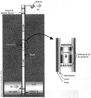
Recent
proposed applications range from the distribution of household goods, mail or
refuse, to inter-city or inter-continental freight movement. Movement of
passengers might also be possible.
The Benefits
Use of PCP
reduces the reliance on trucks for freight transportation. With fewer trucks on
highways and streets, traffic congestion, accidents and air and noise pollution
will all be lessened. Because PCP technology uses underground pipelines powered
by electricity, it does not contribute to highway congestion, is very safe, and
is non-polluting. Furthermore, PCP is far more reliable than trucks, uses less
energy, is weather-proof, theft-proof and
strike-proof. It also gets cargoes to destinations sooner than trucks. It can
be used for transporting hundreds of cargoes that are ordinarily carried by
trucks, such as mail, grain, vegetables, packaged products, bottled milk, boxes
of cans, etc. Therefore, use of PCP in the future for intercity transportation
of freight has vast implications for the nation and the world.
Status
Capsule Pipeline Research
Center
(CPRC) was established at Univ. of Missouri - Columbia
in 1991 to study and develop new pipeline technology for underground
transportation of freight. The Center received
funding from the National Science Foundation (NSF) as a State/Industry
University Cooperative Research Center (State/IUCRC)
for eight years, the longest period of funding for such centers.
Many
companies in the US, Japan, and Canada are still attepting
to not only find market for this technology, but also improve the technology
itself to solve the problems limiting application.
Barriers
Horizontal
PCP
As PCP requires
loading and unloading facilities, a longer distance, say a few km, is necessary
for its economical application. As PCP's acquisition cost is higher than trucks
because it needs pipeline construction as its guide way, a longer operational
year, say a few years, is necessary for its economical application.
Vertical PCP
PCP's cost is
higher than "Bucket-Wire" system if transport distance (depth) is
less than 100 m The main barrier to long-distance PCP
is that the current system is not cost effective as compared to truck and
train, which use existing highways and rails, respectively. To be more
competitive, further improvement of the contempory
PCP systems is needed. This can be done by using electromagnetic pumps (linear
induction motors) instead of blowers to power the system.
Points of
Contact
Henry Liu,
Ph.D., P.E.,
Capsule Pipeline Research Center, College of
Engineering, University of Missouri-Columbia E2421 Engineering Bldg. East
Columbia, Missouri 65211-2200
Phone: (573) 882-1810; 882-2779 Fax: (573) 884-4888;
E-Mail: liuh@missouri.edu
Sanai Kosugi, Dr. Eng., General
Manager
Sumitomo Metals Industry, Ltd., Pipeline Engineering Department Office Tower Y,
Triton Square, 1-8-11, Harumi, Chu Tokyo 160-0003,
Japan
Phone: +81 (3) 4416-6523 Fax: +81 (3) 4416-6781
Email: kosugi-sni@sumitomometals.co.jp
References
CPRC Web site http://www.missouri.edu/~cprc/
Civil Engineering Magazine "Pneumatic Capsule
Pipeline Removes Soil Vertically" Mar. 2002
Tim Howgego. Capsule
Pipeline http://www.capsu.org/
Mining Technology Web site,
http://www.mining-technology.com/contractors/materials/sumitomo/index.html and
http://www.mining-technology.com/contractors/materials/sumitomo/press1.html
More cached texts
Copyright and Usage
Shipping Goes Down The
Tubes
A system for moving goods through a
high-speed pipeline is not so far-fetched, say some researchers.
Linda Rosencrance
Today’s Top Stories  or Other Software Development Stories
-- Imagine a
national network of pipes, some as small as one foot in diameter and half a
mile long, for transporting mail or machine parts between two buildings, and
others as large as six feet in diameter and hundreds of miles long for
intercity and interstate freight shipment. Sound far-fetched?
Not to Professor Henry Liu, director of the Capsule Pipeline Research Center (CPRC) at the University
of Missouri in Columbia. Liu has spent more than 20 years
researching pipeline technology systems in which close-fitting capsules carry
freight through underground tubes between terminals.
As traffic congestion and pollution increase and fossil fuel supplies dry up,
scientists are looking to innovative modes of transportation to transport
freight more cost effectively and efficiently.
"This new pipeline technology can transport freight such as coal; solid
waste, including hazardous waste; [and] agricultural products, as well as mail
and parcels," Liu says.
Two Propulsion Systems
Liu is investigating two capsule propulsion systems to move freight:
pneumatic systems propelled by air pressure, which use air from booster fans or
pumps to move the wheeled capsules through underground tubes, and a slower
hydraulic system.
Hydraulic systems would push freight at 6 to 10 feet per second, while
pneumatic systems would run at much higher speeds - 20 to 50 feet per second,
Liu says.
Freight pipelines would employ a communication system that uses microwaves,
cables and satellites operated automatically by a computer at the pipeline
company's headquarters, he says.
William Vandersteel, an inventor in Alpine, N.J., is
working to improve the technology used in the pneumatic pipeline system. In Vandersteel's tube pipeline, called TubeExpress,
goods are carried in free-wheeling vehicles (capsules) that are pumped through
the pipelines by electrical power. The CPRC is studying the use of an
electromagnetic propulsion system called a linear induction motor, like those
used in roller coasters and high-speed trains, to move freight through the
pipeline, according to Liu.
Using this system, an electromagnetic charge in induction coils set at
intervals within the pipeline would propel the capsules forward. Moving the
capsules directly instead of by pumping air would allow the system to operate
without interruption or distance limitation.
Daryl Oster in Crystal River Fla.,
has invented the Evacuated Tube Transport, which he claims could move goods
from Miami to New York in 25 minutes and from New York to Hong Kong in three or
four hours. Oster says his patented system, which
works by eliminating friction, could be built aboveground as well as
underground.
And while Oster's system - with its promise of speeds
that surpass 2,000 miles per hour - may strain the imagination, there are
already real freight pipelines either in existence or close to development.
Continued...
March 26,
2001
PAGE 2
In the Netherlands, the Dutch
parliament is discussing a freight pipeline project that could link Schiphol Airport in Amsterdam
to the flower market at Aalsmeer. And in Japan, an older pneumatic system, the Sumitomo
Capsule Liner, carries limestone from a mine in Tochigi Prefecture
to a plant 188 miles away, keeping heavy truck traffic off local roads.
But capsule pipelines aren't the only innovative transportation technology that
could be used to move freight.
Francis Reynolds, an engineer and technical inventor in Bellevue, Wash.,
has developed what he calls a "dual-mode" system that would allow
delivery vehicles to be used on streets as well as on "guideways."
Cargo-containing vehicles would travel on automatic guideways
- which would use electricity to power the vehicles - built on a different
level than the streets. The dual-mode vehicles would be battery electric or
fuel cell electric for street use.
"Since we can't get rid of the [vehicles], let's make [vehicles] that
aren't bad," Reynolds says. "They can travel in a normal manner on
local streets, but most of the highway traffic will be done on guideways, where they can travel automatically at 60 mph in
the city and 200 mph on the guideways between
cities."
Reynolds says some dual-mode advocates propose supporting the vehicles on the guideways with pneumatic tires; others propose steel wheels
on steel rails. But many advocates believe that maglev (magnetic levitation) guideways show the most promise, he says.
James Guadagno, a general partner at Paonia, Colo.-based Cimarron
Technology Ltd., has developed the Integrated Transportation System, a
dual-mode system in which vehicles would be propelled by linear synchronous
motors, which would allow vehicles to travel automatically on a guideway at a constant speed.
A Key Partner
Though engineers and inventors are high on new transportation technologies to
move freight, the U.S.
government, which is a necessary partner in the development of new
transportation technology, doesn't share their enthusiasm.
In fact, the U.S. Department of Transportation (DOT) says it isn't doing any
research into any of these systems. The Federal Railroad Administration (FRA)
is, however, exploring the use of maglev vehicles to transport people, says
Arnold Kupferman, manager of the FRA's
maglev program.
According to Kupferman, it would take an act of
Congress for any federal agency to shift its focus to alternative modes of
transportation.
John Fontanella, an analyst at AMR Research Inc. in Boston, says that's not
likely to happen. The reason the government isn't on board with these new
technologies is that none of these systems is economically viable, he says.
But Liu has a different explanation for the lack of government involvement.
"A more possible reason for DOT neglect in freight pipeline research is
the strong lobbying efforts by the trucking industry and the railroad
industry," he says. "They do not want competition from
pipelines."
End
We specialize
in pneumatic capsular pipeline systems. These systems offer lower operating
costs, lower maintenance cost and in many cases lower initial capital cost
compared to other methods of transport. These systems are applied where long
distance covered belt conveyors, some mid-haul truck transport routes and short
haul train systems would be considered
|
A capsule
carrying product is propelled through a pipeline using low pressure air.
These pipelines can transport large quantities for long distances both
horizontally and vertically at a very low operating cost and competitive
capital cost.
Cylindrical
wheeled trucks or capsules are automatically loaded with ore, concentrate,
coal, aggregate, then propelled through a pipeline to be automatically
unloaded at the receiving end.
Capsules
are coupled together in trains, multiple trains run
within the pipeline simultaneously so that the transport system is
continuous.
Multiple
products can be transported in the same and opposite directions
simultaneously without mixing, for the same very low operating cost.
|
|
|
|
|
|
|
|
see simulation, horizontal implementation
|
|
|
|
|

|
|
|

|
|
|
|
These
Pneumatic Capsular Pipelines are used to transport large quantities of
product for long distances.
Typical
applications would include transporting:
|
|
|
|
|
1. Ore, coal, aggregate
from a mine to its mill. Returning tailings to the mine for backfill is
possible, practical, and low cost.
|
|
|
|
|
2.
Concentrates from the mill to a rail or ship load out or directly to the
customer/user.Two or more products can be
transported simultaneously without mixing.
|
|
|
|
|
3. Ore or coal can be
transported from the working face in a mine, to the shaft, up the shaft to
the surface and on to the mill without the product being transferred out of
the capsule. There is a significant reduction in material handling and its
cost. There is a reduction in skip hoist costs.
This system helps ventilate the mine by removing stale, humid, warm air when
the system is hoisting.
|
|
|
|
|
4. Use
where environmental issues prevent all other considerations, for
example, use where the terrain or climate makes other transportation
considerations difficult, impractical or expensive.
|
|
|
|
|
|
|
|
|
see simulation, vertical implementation
|
|
|
|
|

|
|
|
|
|
|
Pneumatic
Capsular Pipelines must be designed by Pneutrans
Systems Limited in order to determine their parameters and economics. User
chosen parameters are usually not practical or economical.
1. Horizontal Distances
|
|
|
A. This
includes inclines and declines.
B. These systems are most practical from 1.5 kilometers (1 mile) in length to
10’s of kilometers/miles in length. Theoretically,there is no limit to the length of these
pipelines.
|
|
|
2. Vertical
Distances
|
|
|
A. This
includes steep inclines.
B. Very practical, can be made to travel at the speed of a skip hoist or
faster. Distances are not a problem.
|
|
|
3. Annual
System Throughput
|
|
|
Can range
from 100,000 tonnes /tons to 12,000,000 tonnes/tons. The most practical range
is 500,000 tonnes/tons to 5,000,000 tonnes/tons.
|
|
|
4. Capsule
Speed
|
|
|
8 to 12
meters (25 to 40 feet per second). Can be made faster when the need arises.
|
|
|
5. Capsule
Payload
|
|
|
Tonnes/tons
depending on pipeline diameter. Capsules or cylindrical trucks are connected
together in trains. Many trains are in transit simultaneously.
|
|
|
6. Pipeline
Diameter
|
|
|
Anywhere
from 406 mm (16 inches) to 1220 mm (48 inches). This is determined by the
annual throughput, time available to transport and the geographical
conditions.
|
|
|
7. Pipeline
Bend Radius
|
|
|
Usually 50
times diameter minimum. It is important to keep the pipeline as straight as
possible.
|
|
|
8. There
are two basic type of systems:
|
|
|
A. Twin
Line Systems: The loaded line runs from ‘A’ to ‘B’ with a separate return
line running from ‘B’ to ‘A’. These are used for extremely heavy-duty
applications. Although they may be practical for some applications, they are
almost twice the capital and operating cost of Single Line Reversing System.
B. Single Line Reversing System: One pipe connects ‘A’ to ‘B’. Capsules are
shuttled back and forth by a reversing airflow. These are used for most
applications. Their capital and operating cost is slightly more then half a
Twin Line system.
|
|
|
9.
Point-to-point pipelines
|
|
|
Typically,
systems are installed as point-to-point pipelines. Switching for multiple
entrances and exits is possible, practical and economical.
|
|
|
10. Loading
and unloading of trains
|
|
|
This is
accomplished by known mining technology.
|
|
|
|
|
|
|
|
|
|
|
|
More papers relying
on Henry Liu's work. It seems this field is his solo domain - apart from
William Vandersteel of NJ who seems to have thought
it all through and costed the system 10 years ago (TubeXpress). There is nothing new under the sun
(below).
Prof Liu also
writes of a system to send Sea-Containers through pipelines. I am intrigued to
see they have square pipes.
Invited
presentation at Summer Meeting of U. S. Transportation Research Board
(TRB)
LaJolla, California, July 10,
2006
- By using
linear induction motor (LIM) capsule pumps, and by using capsule with
steel wheels running on rails, a revolutionized new system of PCP is now
available to transport cargoes of any size, including standard 40-ft
containers, through conduits.
http://www.trb.org/conferences/jointsummer/2006/ports/Session4LIUPaper.pdf
2006 Nova Award
Nomination 20
http://www.cif.org/nom2006/Nom-20-2006.pdf
MID-CONTINENT TRANSPORTATION
SYMPOSIUM 2000 PROCEEDINGS
http://www.ctre.iastate.edu/PUBS/midcon/Liu.pdf
*************************
1980 - 1992
TubeXpress, arguably, is
destined to become the greatest advance in our transportation infrastructure
since the railroad displaced the stagecoach
A major drawback of all air-pumped
systems is the throughput capacity limitation imposed by the valves and
airlocks needed to enable the capsules to bypass the air pumps. The airlocks
required that the capsule(s) be brought to a momentary stop, thereby severely
limiting the throughput of the system and this limitation has been the main
reason why all pneumatic capsule pipeline systems built to date never achieved
commercial success.
A MAJOR TECHNICAL BREAKTHROUGH
In 1980, William Vandersteel
of Alpine, New Jersey, President of TubeXpress
Systems, Inc. and its parent, Ampower Corporation,
invented and patented (U.S. Patent No. 4,458,602, 1984) the embodiment of an
entirely new concept for motivating a capsule pipeline system. Rather than pumping air to propel the
capsules, as had been the practice with every system built up to that time, Vandersteel proposed to impart thrust to the capsules
directly, recognizing that the closely fitting capsules act like pistons in a
long cylinder, and, by imparting thrust to the capsules directly, they will act
like pistons pumping air, thereby motivating other capsules in the line. The
Patent broadly covers any stationary means of imparting thrust to the capsules,
except motivating the capsules by pumping the fluid medium (air).
Though various means of inducing
thrust to the capsules could be considered, Vandersteel
proposed the use of linear induction and/or linear synchronous propulsion,
whereby an electromagnetic thrust is induced in each capsule as it passes over
magnetic induction coils embedded in the base. Propelling the capsules directly
avoids the restriction imposed by the airlocks and valves with the necessity of
stopping the capsules in the airlocks, allowing the system to operate
continuously without interruptions or distance limitation. Propelling the
capsules directly, rather than by pumping the air, is a fundamental advance,
which brings about at least a ten-fold increase in throughput capacity of a
2-meter ID capsule pipeline system. It also explains why, to date, air pumped
capsule pipeline systems have never achieved commercial success. For the first
time, it is now practical to consider capsule pipelines for the automated
transportation of general commodity freight, in direct competition with surface
transport.
The first demonstration of this new
technology was developed by Magplane Technology, Inc.
of Bedford, MA (www.magplane.com) It consists of a
700 ft, 24 inch diameter fiberglass pipeline,
including a 200 ft long accelerator/decelerator section and a load/unloading
station. The capsules are designed to each carry 600 lbs of phosphate rock and
they can move back and forth through the 700 ft test section at up to 40
mph. Capsules are fitted with an array
of neodymium-iron boron permanent magnets, which interact with the linear
synchronous motor mounted external to the tube to provide propulsion and
braking forces. This is a proto-type for a 30-mile system to haul several
million tons per year of phosphate rock from Florida mines to marine terminals for ocean
shipment.
Two basic approaches are possible. Either you start with tunnels wherein the
vehicles (capsules) have a close fit with minimal clearance in the tunnel, or
you start with a cross-section with large clearance to accommodate aerodynamic
constraints. The system with closely
fitting capsules is generally called a pneumatic capsule pipeline system,
generically referred to as “tube freight”. The system operation is similar to a
conveyer as it operates continuously, providing a constant maximum capacity.
Actual the utilization depends on the cargo volume to be transported.
http://www.tubexpress.com/tubexpress.htm
16th
May 2007 – FoodTubes project.
May 08 –
short overview St Andrews: http://www.noelhodson.com/index_files/F-Tubes-StAndrews-1-5-08v7-short.ppt
May 08 –
short http://www.noelhodson.com/index_files/global warming.ppt
Summary
visual – 4 slides: http://www.noelhodson.com/index_files/Foodtubes-All-in-One.ppt
120,000 Homes – City Example – 41 slides: http://www.noelhodson.com/index_files/feb08foodtubes-croydon-v5.ppt
EC Research Proposal: http://www.noelhodson.com/index_files/Foodtubes26JUN07PART-B-V12c.pdf
Summary
Targets: http://www.noelhodson.com/index_files/foodtubes_targets.xls
Calculations,
Logic and Outline: http://www.noelhodson.com/index_files/foodtubes9DEC06.xls
Financial “What-If?” Project Plan: http://www.noelhodson.com/index_files/ftubesfinancials_28Sep07_v15.xls
Pipeline
Symposium Texas:
http://www.noelhodson.com/index_files/isuftmarch2008foodtubes.pdf
State of the
Art report: http://www.noelhodson.com/index_files/StateoftheArt-foodtubes2FEB07.htm
Project Team:
http://www.noelhodson.com/index_files/foodtubes-project-team.htm
Sponsoring
Organizations: http://www.noelhodson.com/index_files/foodtubes-sponsors.htm
Commercial
Construction Consortium: http://www.noelhodson.com/index_files/foodtubes-CCC.htm
Home Page - Main
Proposal: http://www.noelhodson.com/index_files/foodtubes-main-proposal-links.htm
Main Website:
http://www.noelhodson.com


